Automatic sling for guide pillar of reactor core in pressurized water reactor(PWR) nuclear power plant

A pressurized water reactor nuclear power plant and guide column technology, applied in the field of automatic spreader for the core guide column of the pressurized water reactor nuclear power plant, can solve problems such as climbing long ladders, and achieve the effects of reliable function, ingenious and simple structural design, and convenient operation

Pending Publication Date: 2019-02-26
CNNC NUCLEAR POWER OPERATION MANAGEMENT +1
View PDF0 Cites 5 Cited by
  • Summary
  • Abstract
  • Description
  • Claims
  • Application Information

AI Technical Summary

Problems solved by technology

[0003] The purpose of the present invention is to provide an automatic spreader for the core guide column of a pressurized water reactor nuclear power plant, which solves the problem of personnel climbing long ladders in the core area during manual disassembly and unloading, and avoids the high-altitude climbing operation of personnel in the core area , realize the automatic or remote manual tripping and coupling of the guide column, eliminate the risk of personnel falling from high altitude, improve the safety and reliability of the operation, and at the same time, improve the operation efficiency and reduce the radiation dose

Method used


Image

  • Automatic sling for guide pillar of reactor core in pressurized water reactor(PWR) nuclear power plant
  • Automatic sling for guide pillar of reactor core in pressurized water reactor(PWR) nuclear power plant
  • Automatic sling for guide pillar of reactor core in pressurized water reactor(PWR) nuclear power plant

Examples


Embodiment 1

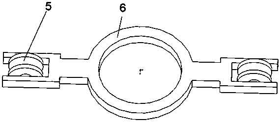
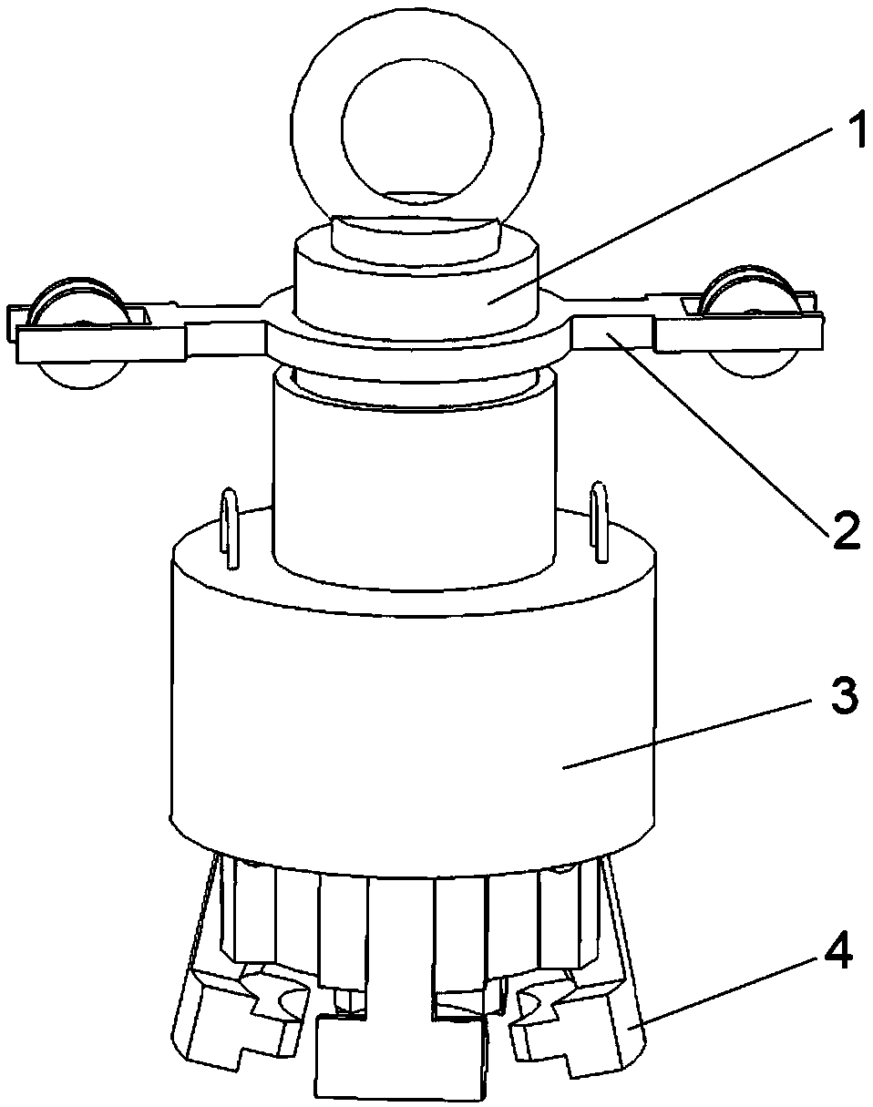
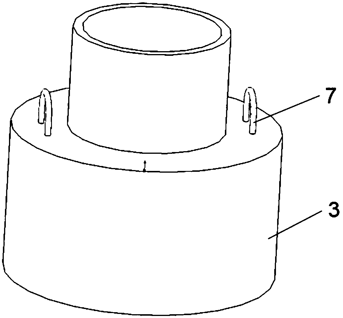
[0023] like Figure 1~5 As shown, an automatic spreader for the core guide column of a pressurized water reactor nuclear power plant, including a spreader center rod 1, a fixed pulley lifting mechanism 2, a drive sleeve 3 and claws 4, wherein the spreader center rod 1 includes a stepped cylinder Structure claw support 8 and the suspension ring 9 fixedly installed on the upper top of the claw support 8, the upper part of the claw support 8 is a cylindrical structure with a slightly smaller diameter, and the side wall of the lower part of the claw support 8 is evenly distributed. A draw-in slot, the width of the draw-in slot is matched with the upper part of the claw 4, and a pin hole is arranged on each draw-in slot, which matches with the pin hole in the upper part of the claw 4, and the claw can be connected by the pin shaft. 4 Installed in the slot of the claw support 8; the drive sleeve 3 is set on the center rod 1 of the spreader, wherein the drive sleeve 3 is a stepped cy...

Embodiment 2

[0026] like Figure 1~5 As shown, an automatic spreader for the core guide column of a pressurized water reactor nuclear power plant, including a spreader center rod 1, a fixed pulley lifting mechanism 2, a drive sleeve 3 and claws 4, wherein the spreader center rod 1 includes a stepped cylinder Structure The claw support 8 and the suspension ring 9 fixedly installed on the upper top of the claw support 8, the upper part of the claw support 8 is a cylindrical structure with a slightly smaller diameter, and the side walls of the lower part of the claw support 8 are evenly distributed with 4 A draw-in slot, the width of the draw-in slot is matched with the upper part of the claw 4, and a pin hole is arranged on each draw-in slot, which matches with the pin hole in the upper part of the claw 4, and the claw can be connected by the pin shaft. 4 Installed in the slot of the claw support 8; the drive sleeve 3 is set on the center rod 1 of the spreader, wherein the drive sleeve 3 is ...


PUM


Abstract

The invention relates to the technical field of guide pillar hoisting of nuclear power plant reactor cores, and specifically discloses an automatic sling for a guide pillar of a reactor core in a pressurized water reactor(PWR) nuclear power plant. The sling comprises a sling center rod, a driving sleeve and clamping claws, wherein the sling center rod comprises a clamping claw support seat of a stagewise cylinder structure; a plurality of clamping slots are uniformly distributed on the side wall of the lower part of the claw support seat; the clamping claws are mounted in the clamping slots ofthe claw support seat in a matching manner by pin shafts; the driving sleeve of a stagewise cylindrical tube structure is sleeved on the sling center rod; and arcs on the inner wall of the driving sleeve are matched with inclined cambered surfaces on the outer side of the clamping claws and the up and down reciprocation of the driving sleeve is switched into the transmission of the clamping clawsaround the pin shafts, thereby realizing that clamping teeth on the inner sides of the clamping claws are meshed with and detached from a circular groove on the lifting ear of an object to be hoisted. The use of the automatic sling changes the past operation mode that a person climbs high to hook the object on the sling, thereby realizing remote control of hooking-on operation and hooking-off operation, and the automatic sling is fast and convenient to operate. At the same time, the structural design is ingenious and simple, the function is reliable, and the operation is convenient.

Description

technical field [0001] The invention belongs to the technical field of nuclear power plant reactor core guide column hoisting, and in particular relates to an automatic spreader for the core guide column of a pressurized water reactor nuclear power plant. Background technique [0002] The core guide column is a cylindrical structure with a height of about 5.5 meters and a weight of 390kg. When not in use, it is stored on the storage rack in the refueling pool. When in use, it is lifted by a crane and installed on the corresponding bolts on the flange surface of the pressure vessel. In the hole, the core guide column is responsible for the guiding and positioning function when the core heavy parts are hoisted. During the hoisting and use of the guide column, there is a problem of difficulty in disconnecting the lug connection of the guide column. When the guide column is hoisted, the operation risk of connecting and disconnecting the lifting lug is high. The lifting lugs of...

Claims


Application Information

Patent Timeline
Patent Type & Authority Applications(China)
IPC IPC(8): G21C19/105G21C19/20
CPCG21C19/105G21C19/20Y02E30/30
Inventor 周围范伟丰孟维民汪微微张晓光安树良董玉良
Owner CNNC NUCLEAR POWER OPERATION MANAGEMENT
Why Eureka
Try Eureka