


Quick Research
Generate reliable direction feasibility study reports for your R&D in just a few steps.

Technical Q&A
Discover and master advanced knowledge NOW. Basics, ideas, possibilities, all at once.

Find Solutions
As an expert in R&D theories, this can generate solutions to your technical problems instantly.

Evaluate Feasibility
Analyze your overall solution with one click, know your potential R&D risks in advance.

Monitor Landscape
Get weekly tech updates, stay abreast of the latest tech innovations and key insights.
IOT (Internet of Things) weighing device and method
A weighing device and Internet of Things technology, applied in the direction of measuring devices, weighing, instruments, etc., can solve the problems of manpower consumption, poor use effect, etc., and achieve the effect of avoiding damage
- Summary
- Abstract
- Description
- Claims
- Application Information
AI Technical Summary
Problems solved by technology
Method used
Image


Examples
Embodiment 1
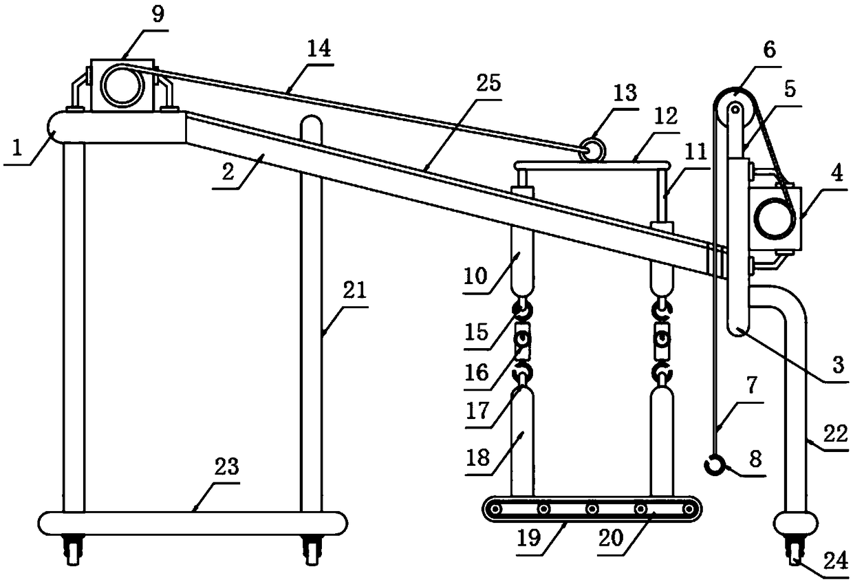
[0029] The present invention provides such Figure 1-3 A weighing device for the Internet of Things shown includes a top plate 1, the side of the top plate 1 is fixedly provided with an inclined plate 2, the end of the inclined plate 2 is fixedly provided with a vertical plate 3, and the side of the vertical plate 3 is fixedly provided with The first winder 4 and the top are fixedly provided with a mounting plate 5, which is movably connected with a fixed pulley 6, and the first winder 4 is provided with a nylon rope 7, and the nylon rope 7 is located on On the outside of the fixed pulley 6, the end of the nylon rope 7 is fixedly provided with a suspension hook 8, and the top of the inclined plate 2 is provided with a U-shaped beam 10, and the top of the U-shaped beam 10 is provided with a connecting rod 11, and the connecting rod 11 A connecting plate 12 is fixed on the top, and a first connecting ring 13 is fixed on the top of the connecting plate 12 , and a steel wire rope ...
Embodiment 2
[0039] A method for weighing the Internet of Things, including the weighing device for the Internet of Things, also includes the following steps:
[0040] S1: Adjust the relative position of the present invention and the heavy object so that the conveyor belt 20 is located on the front side of the heavy object. When the heavy object has a beam structure that can be used to hang the hanging hook 8, the hanging hook 8 can be directly hung on the beam;
[0041] S2: energize the first winding machine 4, and after the first winding machine 4 is energized, it drives the winding wheel to wind up the nylon rope 7, so that the hanging hook 8 at the end of the nylon rope 7 lifts the heavy object;
[0042] S3: Then the user uses a small force to push the heavy object to push the heavy object to the top of the conveyor belt 20;
[0043] S4: Then make the first winding machine 4 unwind, so that the suspension hook 8 is removed from the crossbeam;
[0044] S5: When the weight does not have...
PUM
 Abstract
Description
Claims
Application Information
 - R&D Engineer
- R&D Manager
- IP Professional
- Industry Leading Data Capabilities
- Powerful AI technology
- Patent DNA Extraction
Browse by: Latest US Patents, China's latest patents, Technical Efficacy Thesaurus, Application Domain, Technology Topic, Popular Technical Reports.
© 2024 PatSnap. All rights reserved.Legal|Privacy policy|Modern Slavery Act Transparency Statement|Sitemap|About US| Contact US: help@patsnap.com