Drum vacuum dryer

A drum vacuum and dryer technology, applied in dryers, drying, drying of solid materials, etc., can solve problems such as large heat loss, and achieve the effects of increasing firmness, facilitating drying, and avoiding impact and swing.

Inactive Publication Date: 2019-02-26
张国利
View PDF0 Cites 0 Cited by
  • Summary
  • Abstract
  • Description
  • Claims
  • Application Information

AI Technical Summary

Problems solved by technology

[0003] The hot air convection drying is 4000-7500kj / kg, because convection drying requires hot air to heat the material, and the heat loss due to exhaust is large, and the effective use rate of heat energy in hot air convection drying is generally only 20-50%

Method used


Image

  • Drum vacuum dryer
  • Drum vacuum dryer
  • Drum vacuum dryer

Examples


Embodiment

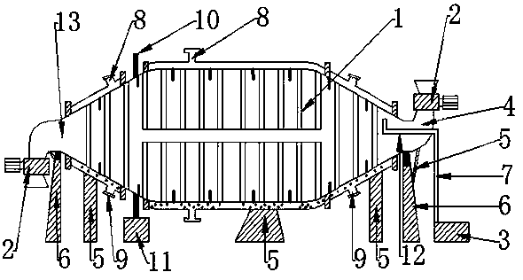
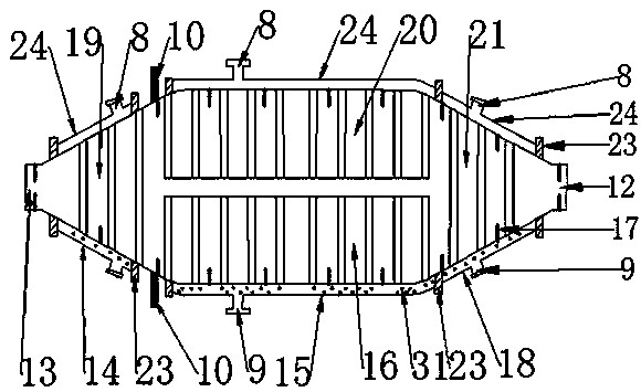
[0166] Such as figure 1 , figure 2 , Figure 6 , Figure 7 The drum vacuum dryer shown includes a drum drying chamber (1), a discharge device (2), a vacuum unit 3), an elbow (4), a bracket (5), a supporting wheel bracket (6), a guide Air pipe (7), gear ring (10), driving device (11), sealing device (23), hopper (32).

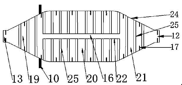
[0167] The drum drying chamber (1) includes a cooling chamber (14), a heating chamber (15), a drying chamber (16), a sealing device (23), and a heat conducting medium (31).

[0168] The drum drying bin (1) has an inlet (12) and an outlet (13); the inlet (12) and outlet (13) of the drum drying bin (1) are also drying bins (16 ) on the inlet (12) and outlet (13).

[0169] The supporting wheel bracket (6) includes a bracket and a supporting wheel.

[0170] 1. The supporting wheel is installed on the bracket.

[0171] Such as figure 1 , figure 2 The gear ring (10) shown is fixedly installed on the drying bin (16), and the gear ring (10) and the drying bin...


PUM


Abstract

The invention relates to a drum vacuum dryer, which comprises a drum drying container, a discharge device, a vacuum unit, an elbow, a bracket, a support wheel bracket, a guide pipe, a gear ring, a driving device, a sealing device and a hopper; the drum drying container includes a heating container, a cooling container, a preheating container, a drying container, a sealing device and a heat conducting medium. The material inlet and outlet of the elbow and the drying container are connected by the dynamic seal fixed by the sealing device. One end of the discharge device is fixedly connected to the flange of the elbow, and the other end of the discharge device is provided with the hopper. One end of the guide pipe is connected to the vacuum unit and the other end extends through the elbow tothe inside of the drying container. The gear ring drives the drying container to rotate on the bracket of the support wheel bracket. The heat energy heats and conducts the material through the heat conducting medium, the heat conversion has the advantages of high efficiency and small loss, thereby improving the material drying speed. After drying, the material is cooled in the cooling section, andthe heat energy released when the material is cooled is capable of being re-utilized. When a heat pipe is damaged and leakage occurs, the use of the whole drum vacuum dryer with cooling section wouldnot be affected.

Description

technical field [0001] The invention relates to a drum dryer, in particular to a drum vacuum dryer. Background technique [0002] Nowadays, materials such as grain, food, chemical industry, medicine, agricultural and sideline products, pasture and so on need to be heated and dried in the field of processing and production; most of the drying chambers of the drying equipment on the market are heat-exchanged with row-type heat-dissipating standpipes However, their radiators have large volume, small heat dissipation area, and low efficiency of heat energy use. If the heat dissipation riser in the drying chamber leaks, it is not easy to repair, which will cause the tumble dryer to be scrapped and cannot be used. The heating device of the tumble dryer is installed on the drying site of the tumble dryer, which reduces the use efficiency of the drying site of the tumble dryer and causes environmental pollution of the drying site of the tumble dryer. The material is cooled in a no...

Claims


Application Information

Patent Timeline
Patent Type & Authority Applications(China)
IPC IPC(8): F26B17/32F26B23/10F26B25/04
CPCF26B17/32F26B23/10F26B25/04Y02P70/10
Inventor 张国利
Owner 张国利
Why Eureka
Try Eureka