
Butterfly valve

A butterfly valve and valve body technology, applied in the field of butterfly valves, can solve problems such as poor sealing performance, and achieve the effects of good sealing performance, good manufacturing process, and small opening torque

Pending Publication Date: 2019-02-26
SHANGHAI HONGYAN RETURNABLE TRANSIT PACKAGINGS CO LTD
View PDF0 Cites 3 Cited by
  • Summary
  • Abstract
  • Description
  • Claims
  • Application Information

AI Technical Summary

Problems solved by technology

[0002] The opening method of the existing butterfly valve is that the middle shaft of the valve core rotates, driving the two sides of the valve core to rotate and open, and the sealing performance is usually poor
Especially when the butterfly valve is mainly made of plastic, its sealing performance is worse after high-temperature sterilization

Method used


Image

  • Butterfly valve
  • Butterfly valve
  • Butterfly valve

Examples


Embodiment Construction

[0037] Preferred embodiments of the present invention will be described in detail below with reference to the accompanying drawings, so as to better understand the purpose, features and advantages of the present invention. It should be understood that the embodiments shown in the drawings are not intended to limit the scope of the present invention, but only to illustrate the essence of the technical solutions of the present invention.

[0038] In the following description, for the purposes of explaining the various disclosed embodiments, certain specific details are set forth in order to provide a thorough understanding of the various disclosed embodiments. One skilled in the relevant art will recognize, however, that an embodiment may be practiced without one or more of these specific details. In other instances, well-known devices, structures and techniques associated with the present application may not have been shown or described in detail in order to avoid unnecessarily...


PUM


Abstract

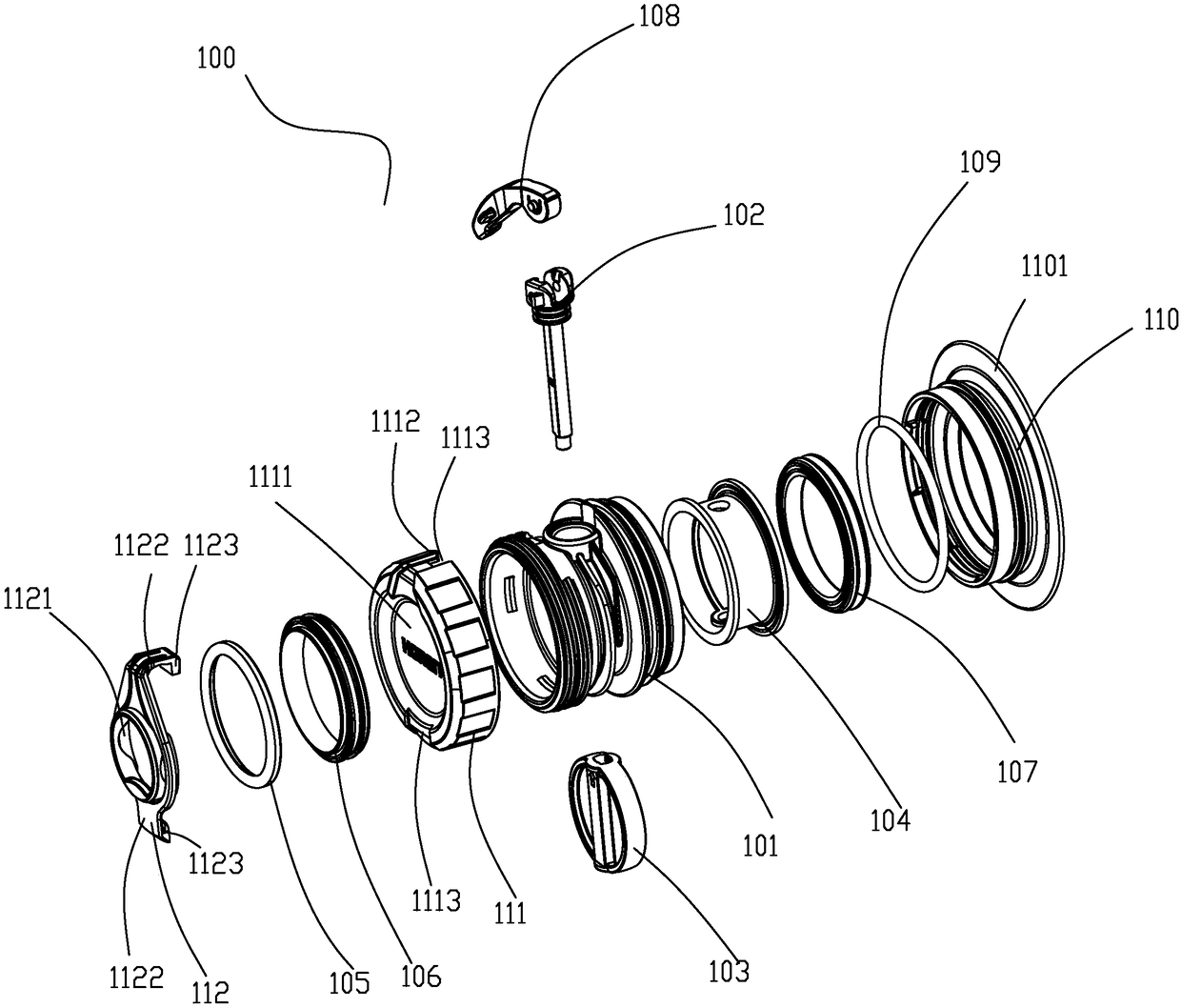
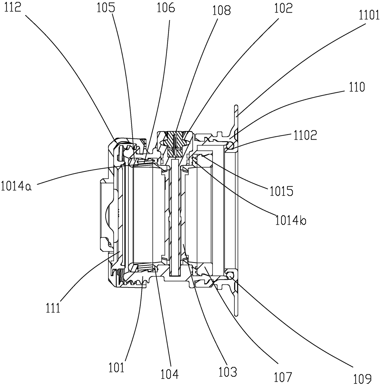
The invention discloses a butterfly valve. The butterfly valve comprises a valve body, an inner valve seat, a valve core, a valve rod and at least one positioning ring. The valve body has an inlet endand an outlet end and an axial passage communicating the inlet end and the outlet end. The valve body is provided with a valve rod mounting hole along the radial direction, between the inlet end andthe outlet end. And a valve seat mounting part is arranged in the valve body, at a position corresponding to the valve rod mounting hole. The inner valve seat is fixedly arranged on the valve seat mounting part and is a cylindrical piece, and the side wall of the inner valve seat is provided with a radial through hole corresponding to the valve rod mounting hole. The valve core is a plate-shaped element and is installed in the inner valve seat, wherein a through hole in the radial direction is formed in the plate-shaped element. The valve rod sequentially passes through the valve rod mountinghole, the through hole of the inner valve seat and the through hole of the valve core; the positioning ring is arranged in the valve body, on the axial side surface of the inner valve seat and forms asealing connection with the inner valve seat. The butterfly valve has good sealing performance.

Description

technical field [0001] The invention relates to a valve, in particular to a butterfly valve. Background technique [0002] The opening method of the existing butterfly valve is that the middle rotating shaft of the valve core rotates, which drives the two sides of the valve core to rotate and open, and the sealing performance is usually poor. Especially when the butterfly valve is mainly made of plastic, its tightness will be worse after high-temperature sterilization. Contents of the invention [0003] The purpose of the present invention is to provide a butterfly valve with good sealing performance. [0004] To achieve the above object, the present invention provides a butterfly valve, which includes: [0005] A valve body, the valve body has an inlet port and an outlet port and an axial channel communicating with the inlet port and the outlet port, on the valve body there is a radial channel between the inlet port and the outlet port The valve stem installation hole ...

Claims


Application Information

Patent Timeline
Patent Type & Authority Applications(China)
IPC IPC(8): F16K1/226F16K1/36F16K1/42F16K1/32F16K27/02
CPCF16K1/2263F16K1/32F16K1/36F16K1/42F16K27/0218F16K1/2265F16K35/00F16K31/602
Inventor 不公告发明人
Owner SHANGHAI HONGYAN RETURNABLE TRANSIT PACKAGINGS CO LTD
Learn More