
Advanced brake override device and method

An advanced, brake switch technology, applied in the direction of automatic starting device, braking action starting device, power plant control mechanism, etc., can solve the problem of brake not working, so as to ensure the normal operation of the brake and prevent major traffic accidents.

Active Publication Date: 2019-02-26
(株)韩中NCS
View PDF5 Cites 0 Cited by
  • Summary
  • Abstract
  • Description
  • Claims
  • Application Information

AI Technical Summary

Problems solved by technology

However, if the accelerator pedal and the brake pedal are pressed at the same time when the car is rushing, the brake may not work because the electronic control unit (ECU) cannot process the brake signal in time, thus causing a major traffic accident.

Method used


Image

  • Advanced brake override device and method
  • Advanced brake override device and method

Examples


Embodiment

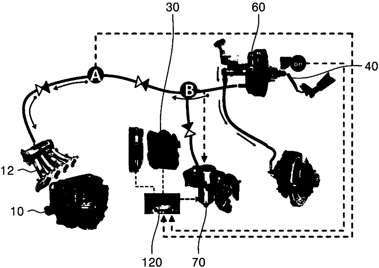
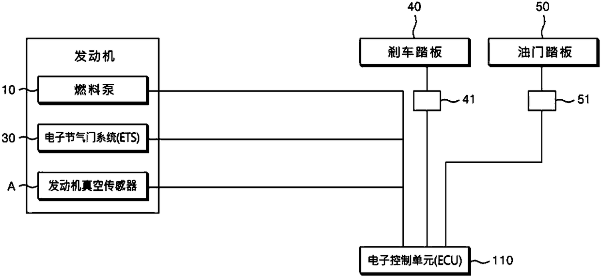
[0057] When the electronic control unit 110 receives the braking signal, if the vacuum value of the engine vacuum sensor A is low, it will record a low vacuum event. The electronic control unit 110 can output a warning message reminding to check the braking system when the number of recorded low vacuum events exceeds a certain number of times.

[0058] Warning messages can be transmitted to the driver's smartphone via a wireless communication module. When the driver's smartphone receives the warning message, it can use the GPS module to measure the location of the vehicle and recommend the repair center closest to the measured location by searching the repair center database.


PUM


Abstract

The present invention relates to an advanced brake priority device and method thereof, wherein the device includes an engine (10) mounted with an exhaust manifold (11) and an intake manifold; an engine vacuum sensor (A) for monitoring the vacuum state of the intake manifold; an electronic control unit (ECU, 110) for receiving the vacuum value of the engine vacuum sensor (A) and the brake signal ofthe brake switch (41) of the brake pedal (40); an electronic throttle system (ETS, Electric Throttle System, 30) for adjusting the amount of air flowing into the engine (10). The electronic control unit (ECU, 110) preferentially receives the brake switch by controlling the signal of the accelerator pedal (50) when the engine vacuum value is less than a preset standard value and the brake signal of the brake switch (41) is simultaneously received.

Description

technical field [0001] The present invention relates to an advanced brake priority device and its method, in particular to an advanced brake priority device and its method capable of ensuring the brake priority operation under any circumstances such as pressing the accelerator pedal and the brake pedal at the same time. Background technique [0002] The vehicle's braking system is used to slow down the engine and stop the movement of the wheels. As an example of the work of the brake system, when the accelerator pedal and the brake pedal are pressed at the same time, the electronic control unit (ECU) will work in a priority mode that processes the brake signal first. However, if the accelerator pedal and the brake pedal are stepped on simultaneously when the car is rushing, the brake may not work because the electronic control unit (ECU) cannot process the brake signal in time, thereby causing a major traffic accident. [0003] Prior art literature [0004] patent document...

Claims


Application Information

Patent Timeline
Patent Type & Authority Applications(China)
IPC IPC(8): B60T7/12B60T17/22F02D41/00F02D41/22
CPCB60T7/12B60T17/22F02D41/0002F02D41/22F02D2041/227F02D2200/0404F02D2200/0406F02D2200/602Y02T10/40B60K26/02B60K28/14B60T7/042F02D41/222F02D2011/103
Inventor 金焕植金焕燮姜弼琇申炯均徐中铉
Owner (株)韩中NCS
Learn More