
Tube locating device

A positioning device and pipe technology, applied in the field of machinery, can solve problems such as waste of processing, increased production costs, poor fit of clamping devices, etc., and achieve the effects of reasonable overall structure design, guaranteed use strength, and reasonable structural design

Inactive Publication Date: 2019-02-26
陈振清
View PDF0 Cites 5 Cited by
  • Summary
  • Abstract
  • Description
  • Claims
  • Application Information

AI Technical Summary

Problems solved by technology

[0003] The existing clamping device does not fit well with other components, resulting in waste of machining and increased production costs

Method used


Image

  • Tube locating device

Examples


Embodiment Construction

[0021] The present invention will be further explained below in conjunction with the accompanying drawings and embodiments.

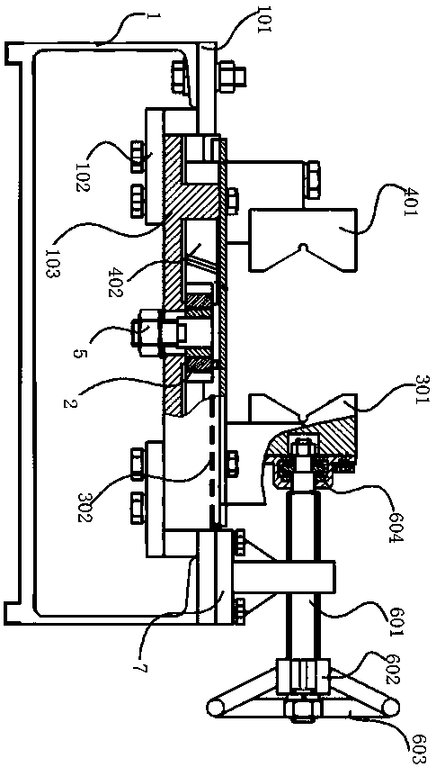
[0022] Such as figure 1 As shown, a pipe positioning device includes a support 1, an adjustment gear 2, a driven unit and an active unit arranged on the support, and a power device compatible with the active unit; the active unit: includes an active V-shaped clamp Block 301, the active rack 302 fixedly connected with the active V-shaped clamp block 301, the adjusting gear 2 adapted to the active rack 302; the driven unit: including the driven V-shaped clamp block 401, and the driven V-shaped clamp block 401. The driven rack 402 fixedly connected to the block 401, the adjusting gear 2 adapted to the driven rack 402; the active unit drives the driven unit to move through the adjusting gear 2; The device includes a manually adjustable lead screw structure or an electric motor power device.

[0023] The support 1 is provided with a positioning platform 10...


PUM


Abstract

The invention discloses a tube locating device. The tube locating device comprises a support, a regulating gear, a driven unit and a drive unit both arranged on the support, and a power device adaptedto the drive unit; the drive unit comprises a drive V-shaped clamping block, a drive rack fixedly connected with the drive V-shaped clamping block, and a regulating gear adapted to the drive rack; the driven unit comprises a driven V-shaped clamping block, a driven rack fixedly connected with the driven V-shaped clamping block, and a regulating gear adapted to the driven rack; the drive unit drives the driven unit through the regulating gear to move; the power device is in transmission connection with the drive V-shaped clamping block; and the power device comprises a manual regulating screwstructure or a motor power device. The tube locating device is reasonable in structure design, the drive V-shaped clamping block is driven by the power device to move, and the drive V-shaped clampingblock drives the drive rack to drive the regulating gear to rotate, so that the driven rack is driven to move, and the distance of the driven V-shaped clamping block relatively to the drive V-shaped clamping block is driven to be increased to reduced.

Description

technical field [0001] The invention relates to the mechanical field, in particular to a pipe positioning device. Background technique [0002] When processing pipes and fittings, it needs to be cut to length, but because pipes are generally welded by steel plates or steel strips, clamping deformation or plastic deformation will occur when cutting to length; therefore, the feeding device when cutting to length and clamping devices are particularly important. [0003] The existing clamping device has poor coordination with other components, resulting in waste of processing and increased production costs. Contents of the invention [0004] The purpose of the present invention is to overcome the problems of the prior art and provide a pipe positioning device. [0005] A pipe positioning device of the present invention includes a support, an adjustment gear, a driven unit and an active unit arranged on the support, and a power device matched with the active unit; the active ...

Claims


Application Information

Patent Timeline
Patent Type & Authority Applications(China)
IPC IPC(8): B23Q3/06
CPCB23Q3/06B23Q3/062B23Q3/064
Inventor 陈振清
Owner 陈振清
Learn More