
Design method of double-sided arcuate band clearance for micro-turbojet engines

A technology of a turbojet engine and a design method, which is applied in the directions of calculation, special data processing applications, instruments, etc., can solve the problem that the tightening force of the strap cannot be used with the tightening torque of the fixed bolt, the restraint force of the strap on the engine is difficult to control, and the upper and lower straps cannot be controlled. Inability to close and other problems to achieve the effect of improving material utilization, achieving lightweight, and improving inclusiveness

Active Publication Date: 2019-02-22
SICHUAN AEROSPACE ZHONGTIAN POWER EQUIP CO LTD
View PDF2 Cites 0 Cited by
  • Summary
  • Abstract
  • Description
  • Claims
  • Application Information

AI Technical Summary

Problems solved by technology

Especially for the control of the band gap, it often happens that the band gap is too small, and asbestos pads need to be added for adjustment, or the gap is too large, and the upper and lower bands cannot be closed, which deteriorates the stress on the bolts, and even breaks during installation. Bolt or strap failure occurs
At the same time, during the installation of the strap, since the tension bolt is not only subjected to tensile load but also to bending load during the working process, the tension of the strap cannot be controlled by fixing the tightening torque of the bolt
Therefore, when the gap between the bands is inconsistent due to manufacturing errors and other reasons in a batch of bands, the binding force provided by the bands on the engine will also be difficult to control

Method used

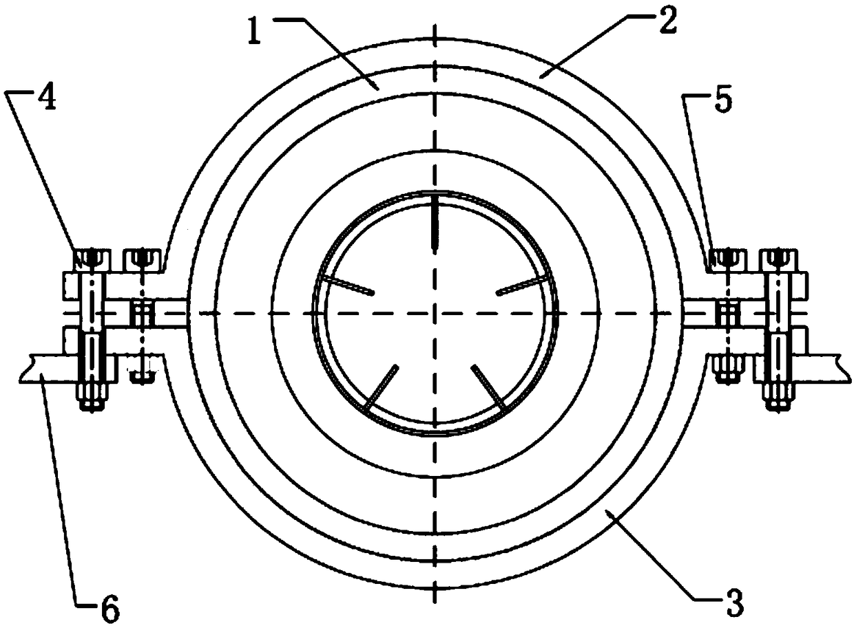
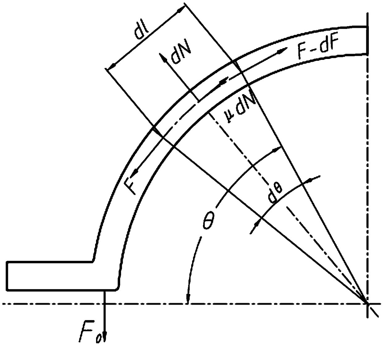

Image

  • Design method of double-sided arcuate band clearance for micro-turbojet engines
  • Design method of double-sided arcuate band clearance for micro-turbojet engines
  • Design method of double-sided arcuate band clearance for micro-turbojet engines

Examples


Embodiment 1

[0172] The relevant parameters involved in a certain type of micro-turbojet engine band are as follows:

[0173] Engine mass: m=10kg;

[0174] Axial shock acceleration: a=2000m / s 2 (200g);

[0175] Friction coefficient: μ=0.08;

[0176] Shell outer diameter: R=102;

[0177] Number of strap groups: n=2;

[0178] Material elastic modulus: E=196GPa;

[0179] Material yield limit: σ s =198MPa;

[0180] Band cross-sectional area: S=Bt=1×10 -3 ×15×10 -3 =1.5×10 -5 m 2 ;

[0181] Band inner diameter:

[0182] Shell outer diameter:

[0183] The expression of the relationship between the constraint force required by the engine and the theoretical minimum clearance of the strap is:

[0184]

[0185] The input data are:

[0186]

[0187] The formula for calculating the theoretical maximum clearance of the hoop is:

[0188]

[0189] Check the uniaxial tensile stress-strain curve of 1Cr18Ni9Ti (attached Figure 5 ) shows that 1.5σ s The corresponding strain v...


PUM


Abstract

A Design method of double-sided arcuate band clearance for micro-turbojet engines features that the theoretical minimum clearance of band is calculate by considering the circumferential tension loss caused by friction force aft the band is installed according to the restriction required by engine system, and the clearance of arcuate band is calculated according to the circumferential tension losscaused by friction. Based on the strength analysis and design criterion of elastic-plastic shakedown theory, under the condition of ensuring the safe operation of the structure, a certain amount of plastic deformation is allowed to occur in the local area of the structure, and the theoretical maximum clearance of the band is calculated. Considering the manufacturing error between the shell and theband, the minimum gap and the maximum gap of the band are calculated. Finally, between the design minimum clearance and the design maximum clearance, the optimal design clearance is determined by weighting coefficient. By using the optimum clearance value given by the clearance amount design method described in the patent of the invention, the precise control of the binding force of the band on the engine can be realized, and the qualification rate of the band manufacture can be greatly improved.

Description

technical field [0001] The invention belongs to the field of mechanical manufacturing, and in particular relates to a method for designing the clearance of a double-sided bow-shaped band for a micro-turbojet engine, which is suitable for the design and manufacturing process of the bow-shaped band of a micro-turbojet engine. Background technique [0002] Micro-turbojet engines used for UAVs and cruise missiles are usually connected to the overall body with a bow-shaped strap. The strap is responsible for transmitting the thrust of the engine system to the overall body. Large impact load, so the reliability of the connection between the engine system and the whole is particularly critical. [0003] At present, the double-sided bow-shaped straps for micro-turbojet engines mainly rely on experience for preliminary design, and then make feedback corrections based on environmental test results. Especially for the control of the band gap, it often happens that the band gap is too ...

Claims


Application Information

Patent Timeline
Patent Type & Authority Applications(China)
IPC IPC(8): G06F17/50
CPCG06F30/17
Inventor 熊杰刘驰刘颖陈腾
Owner SICHUAN AEROSPACE ZHONGTIAN POWER EQUIP CO LTD
Learn More