
A method for determining the usable limit of crack-type hard object damage on the leading and trailing edges of blades considering high and low cycle fatigue

A technology of low cycle fatigue and determination method, which is applied in the direction of applying repetitive force/pulsation force to test the strength of materials, instruments, measuring devices, etc., which can solve the problems of tearing/crack-type hard object damage, lack of reasonable specification and available limit formulation process, etc.

Active Publication Date: 2020-02-21
NANJING UNIV OF AERONAUTICS & ASTRONAUTICS
View PDF8 Cites 0 Cited by
  • Summary
  • Abstract
  • Description
  • Claims
  • Application Information

AI Technical Summary

Problems solved by technology

[0006] The purpose of the present invention is to provide a method for determining the available limit of crack-type hard object damage at the leading and trailing edge of the blade considering high and low cycle fatigue, so as to solve the problem that there is currently no reasonable and standardized available limit formulation process for tear / crack type hard object damage

Method used


Image

  • A method for determining the usable limit of crack-type hard object damage on the leading and trailing edges of blades considering high and low cycle fatigue
  • A method for determining the usable limit of crack-type hard object damage on the leading and trailing edges of blades considering high and low cycle fatigue
  • A method for determining the usable limit of crack-type hard object damage on the leading and trailing edges of blades considering high and low cycle fatigue

Examples


Embodiment

[0051] A method for determining the usable limit of crack-type hard object damage at the leading and trailing edges of a blade considering high and low cycle fatigue, comprising the following steps:

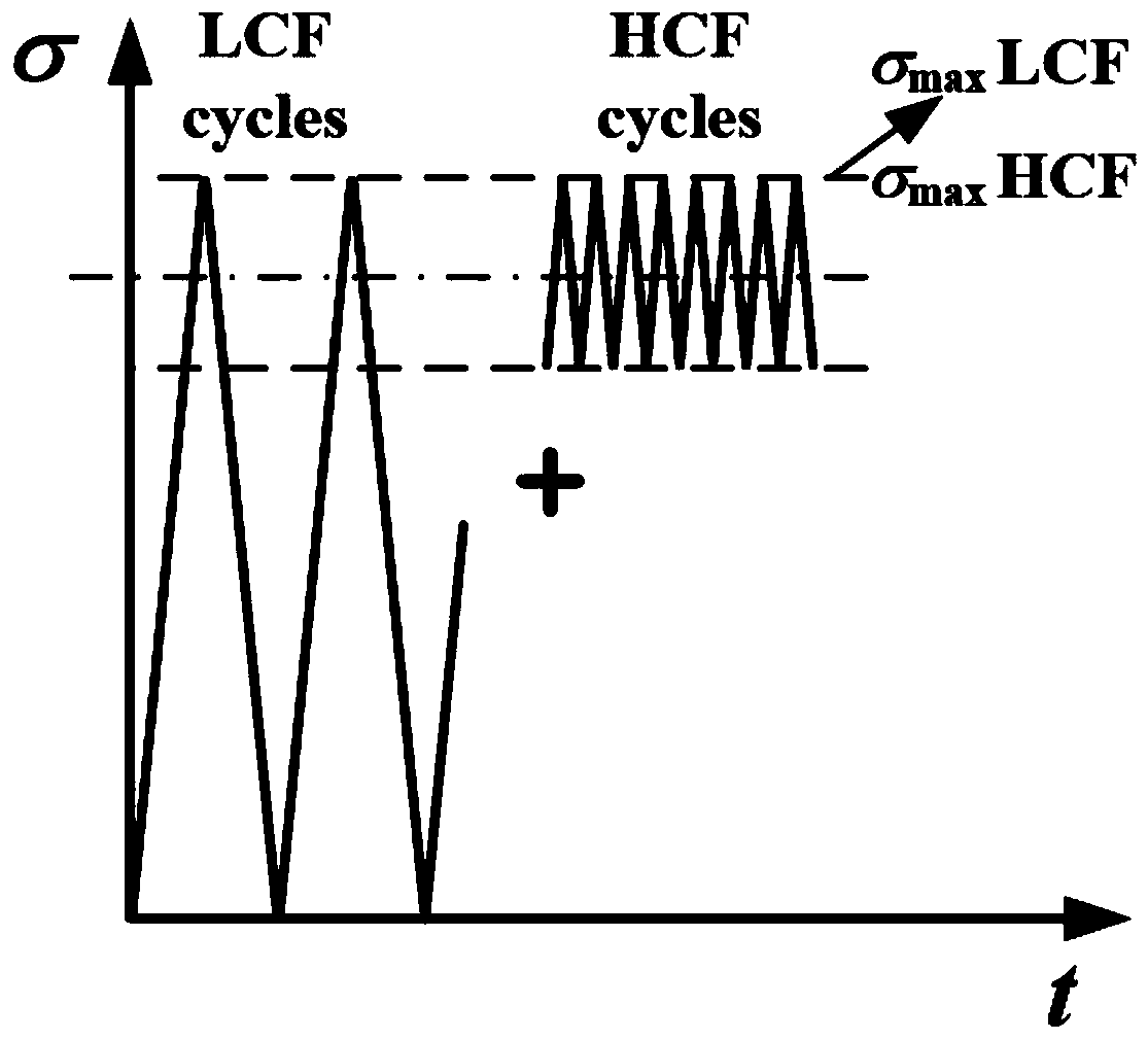
[0052] (1) The possible high-cycle fatigue load and low-cycle fatigue load are extracted from the high / low-cycle composite fatigue loads borne by each point on the leading and trailing edges of the blade. Among them, high cycle fatigue load is high cycle fatigue load, referred to as HCF, and low cycle fatigue load is low cycle fatigue load, referred to as LCF.

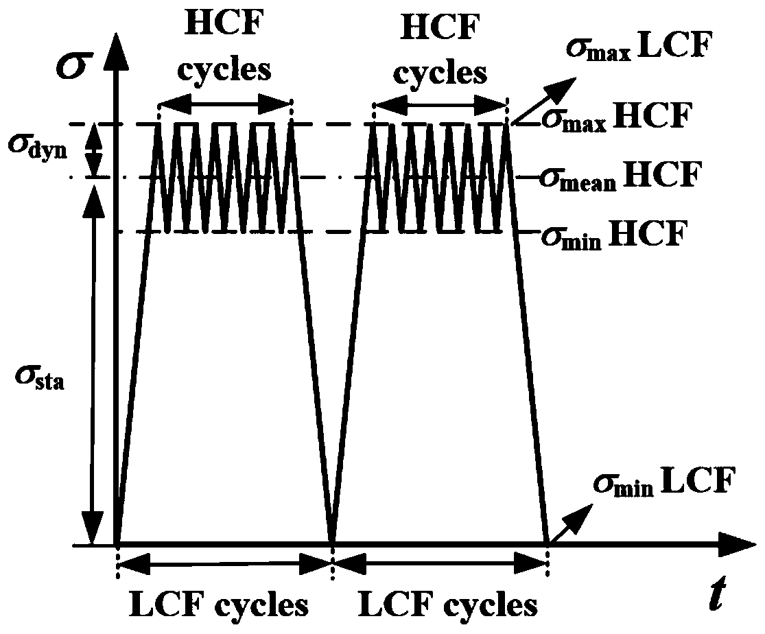
[0053] The high / low cycle composite load of the blade refers to the interaction between the low frequency centrifugal force cycle load and the high frequency vibration load of the blade when the engine is working normally, such as figure 1 shown. In the present invention, the centrifugal force cyclic load in the blade is recorded as low cycle fatigue load, i.e. low cycle fatigue load, and the high frequency vibration loa...


PUM


Abstract

The invention discloses a method for determining an available limit of crack-type hard object damage of leading and trailing edges of a blade by taking high and low cycle fatigue into account. The method comprises the steps: firstly, extracting high-cycle-fatigue loads and low-cycle-fatigue loads from high / low-cycle composite loads borne by the blade, and respectively establishing a crack / tear-type hard object damage crack non-extension equivalent curve relevant to a stress ratio under a series of high-cycle-fatigue loads and low-cycle-fatigue loads; then, determining a static stress and a dynamic stress on a position of each point of the leading and trailing edges of the blade by using a finite element numerical analysis method; and finally, comparing positions of the static stress and the dynamic stress in the crack non-extension equivalent curve to determine a crack size corresponding to the equivalent curve, namely the available limit of crack / tear-type hard object damage at the point of the leading and trailing edges of the blade. The invention not only provides the simple and effective method for determining the available limit of the hard object damage, but also forms a normalized available limit formulation process for the crack / tear-type hard object damage of the leading and trailing edges of the blade.

Description

technical field [0001] The invention relates to a method for determining the available limit of crack-type hard object damage at the front and rear edges of a blade considering high and low cycle fatigue, and belongs to the field of damage tolerance design and maintenance of aeroengine blade hard objects. Background technique [0002] Metal, fragments, gravel, stones and other hard objects enter the engine airflow channel along with the airflow, and the impact damage caused by the collision with the high-speed rotating blade is one of the important reasons for aggravating the fatigue failure of the blade. Although people have put forward foreign object damage prevention measures such as airstrip foreign object cleaning, ground crew maintenance tool inspection and control, etc., hard object damage is always inevitable. [0003] For the inevitable hard object damage, although the engine designer has made the blades have a certain hard object damage tolerance capability, it is ...

Claims


Application Information

Patent Timeline
Patent Type & Authority Patents(China)
IPC IPC(8): G01N3/32
CPCG01N3/32G01N2203/0005G01N2203/0066G01N2203/0073
Inventor 宋迎东贾旭胡绪腾嵇大伟吴娜
Owner NANJING UNIV OF AERONAUTICS & ASTRONAUTICS
Learn More