
A material level measuring device and a material conveying system

A material level measurement and drive system technology, used in measurement devices, measurement of ultrasonic/sonic/infrasonic waves, liquid level indicators for physical variable measurement, etc. The problem of granular material or powder material level height, etc., can solve the problem that the material level cannot be accurately measured and the sealing performance is good.

Active Publication Date: 2020-08-14
ENN SCI & TECH DEV
View PDF8 Cites 0 Cited by
  • Summary
  • Abstract
  • Description
  • Claims
  • Application Information

AI Technical Summary

Problems solved by technology

However, due to the high-temperature and high-pressure environment inside these containers, for example, the temperature in the raw coal hopper and the slagging storage tank is as high as 500-1500°C, and the pressure is as high as 5-15Mpa, and the sensors and these measuring components cannot work under high-temperature and high-pressure conditions, and will The installation of sensors or other auxiliary measurement components inside the storage tank is also not conducive to the sealing of the high-pressure environment, so the current material level measurement device cannot be used to measure the material level of solid phase particles or powder in high-temperature and high-pressure containers

Method used


Image

  • A material level measuring device and a material conveying system
  • A material level measuring device and a material conveying system

Examples


Embodiment 1

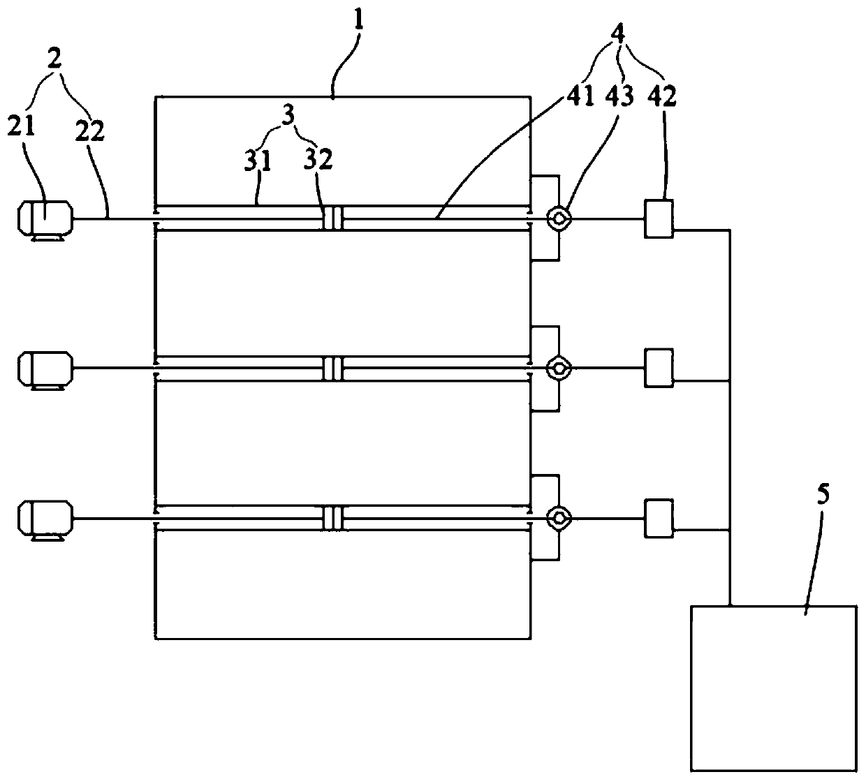
[0033] refer to figure 1 As shown, as an embodiment, the vibration detection system 4 includes a swing transmission rod 41 and a vibration detection unit 42 , one end of the swing transmission rod 41 is connected to the vibration tube 31 or the moving part 32 , and the other end is connected to the vibration detection unit 42 .

[0034] It should be noted here that the swing transmission rod 41 can be connected to the moving part 32 or the vibrating tube 31, and figure 1 In the illustration, only the swing transmission rod 41 can be connected to the moving part 32 is taken as an example for illustration, as long as the vibration tube 31 or the moving part 32 vibrates to drive the swing transmission rod 41 to vibrate synchronously.

[0035] Since the vibrating tube 31 or the moving part 32 is connected to one end of the swing transmission rod 41, the vibrating tube 31 or the moving part 32 can transmit the vibration information to the vibration detection unit 42 connected to th...

Embodiment 2

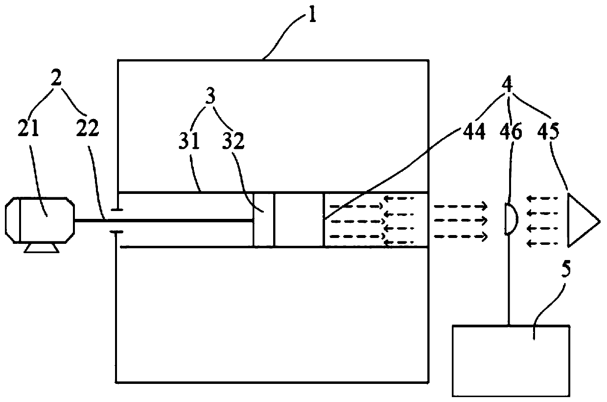
[0052] refer to figure 2 As shown, as another embodiment, the vibration detection system 4 includes a reflective mirror 44 arranged on the moving part 32 or the vibrating tube 31, and a detection light source 45 and a light sensor 46 arranged outside the container 1 to be tested. When the driving system 2. When not working, the light emitted by the detection light source 45 is irradiated on the reflective mirror 44, and the reflective mirror 44 can reflect the light irradiated on it to the photosensitive element 46.

[0053] When the drive system 2 is working, if the material level in the container 1 to be tested does not reach the position of the vibrating tube 31, that is, the vibrating tube 31 does not contact the material inside the container 1 to be tested, then the moving part 32 and the vibrating tube 31 are in a vibrating state. When the vibrating tube 31 is in a vibrating state, the vibrating tube 31 is not straight, so that the light emitted by the detection light s...


PUM


Abstract

The invention discloses a material level measuring device and a material conveying system, and relates to the technical field of material level measurement. The material level measuring device can measure the material level height of solid-phase granules or powder in a high-temperature and high-pressure container. The material level measuring device is used for detecting the material level heightin the to-be-detected container, and comprises a driving system, a vibration assembly and a vibration detection system; the vibration assembly comprises a vibration pipe which is located inside the to-be-tested container and a movement part which is located inside the vibration pipe, the two ends of the vibration pipe penetrate through the to-be-tested container and are in sealed connection with the outer wall of the to-be-tested container, the driving system and the vibration detection system are located outside the to-be-tested container, the driving system is used for driving the movement part to move to drive the vibration pipe to vibrate, and the vibration detection system is used for detecting vibration information of the vibration assembly. The material level measuring device and the material conveying system are used for measuring the material level height in the container.

Description

technical field [0001] The invention relates to the technical field of material level measurement, in particular to a material level measurement device and a material delivery system. Background technique [0002] In the industrial production process, it is often necessary to measure the material level of solid phase particles or powder in high temperature and high pressure containers. For example, in the field of coal chemical industry, it is often necessary to measure the material level in raw coal hoppers and slag discharge storage tanks. [0003] When the material level measuring device disclosed in the related art works, a sensor or other auxiliary measuring components need to be built into the container to be measured. However, due to the high-temperature and high-pressure environment inside these containers, for example, the temperature in the raw coal hopper and the slagging storage tank is as high as 500-1500°C, and the pressure is as high as 5-15Mpa, and the senso...

Claims


Application Information

Patent Timeline
Patent Type & Authority Patents(China)
IPC IPC(8): G01F23/22G01H9/00B65D90/48
CPCB65D90/48G01F23/22G01H9/00
Inventor 张立明马明水李克忠
Owner ENN SCI & TECH DEV
Learn More