Turbine baffle plate with embedded thermal insulating pipe

A technology of thermal insulation pipe and turbine, which is applied to the supporting elements of blades, engine elements, machines/engines, etc., and can solve the problems of separation of turbine baffles and wheel disc positioning surfaces.

Active Publication Date: 2019-02-22
AECC SICHUAN GAS TURBINE RES INST
View PDF4 Cites 3 Cited by
  • Summary
  • Abstract
  • Description
  • Claims
  • Application Information

AI Technical Summary

Problems solved by technology

[0006] The invention is used for the baffle of the turbine rotor of the aero-engine, changes the thermal response speed of the thin-walled turbine baffle in the acceleration-deceleration process of the engine, improves the temperature difference between the turbine baffle and the wheel disc, and thus solves the problem caused by thermal incongruity The separation between the turbine baffle and the wheel disk positioning surface caused by the large-area plastic deformation of the radial positioning boss of the turbine baffle and the central area

Method used


Image

  • Turbine baffle plate with embedded thermal insulating pipe
  • Turbine baffle plate with embedded thermal insulating pipe
  • Turbine baffle plate with embedded thermal insulating pipe

Examples


Embodiment Construction

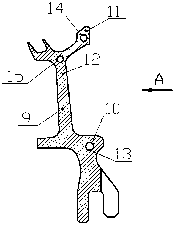
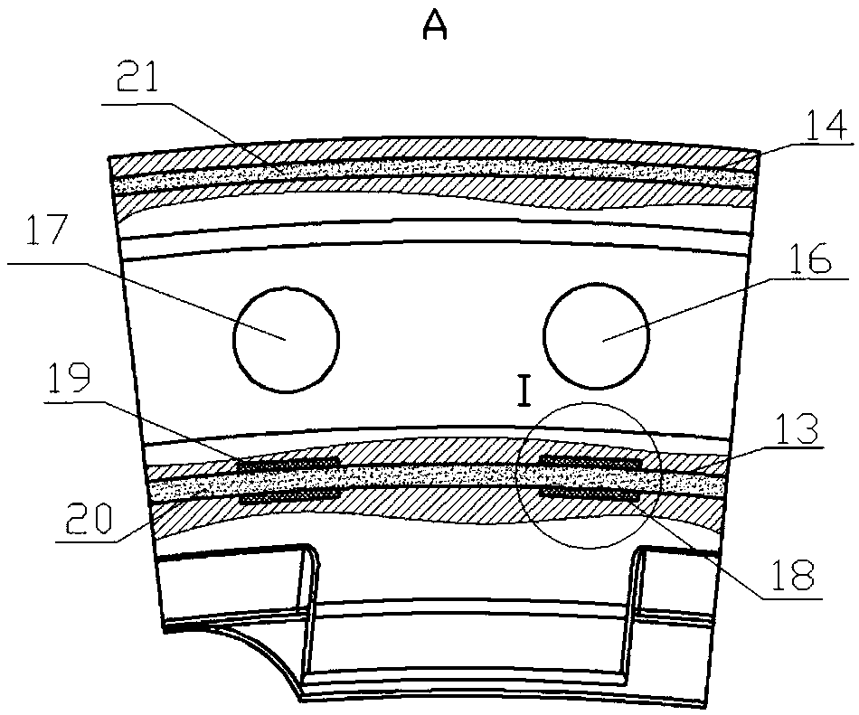
[0020] Such as Figure 2-Figure 4 As shown, a cavity 13 is processed in the radial positioning boss 10 of the built-in insulation tube turbine baffle 9 of the present invention, the cavity 13 extends along at least the circumferential direction, and a certain amount of heat preservation medium 20 is injected into the cavity 13, Form the insulation tube. On the outer surface of the cavity 13 in the radial positioning boss 10, a section of slow-release sleeve 18 or 19 whose thermal conductivity is lower than the material of the turbine baffle is set at a circumferential position corresponding to the turbine baffle air hole 16 or 17, and the slow-release The sleeves 18 or 19 surround at least a part of the circumferential surface of the cavity 13, the number of which is the same as the number of the turbine baffle vents 16 or 17, the length of each section is equal, and they are uniformly distributed along the circumferential direction. When the engine accelerates, the temperatu...


PUM


Abstract

The invention discloses a turbine baffle plate with an embedded thermal insulating pipe. The thermal insulating pipe is arranged in a radial positioning boss of the turbine baffle plate, extends in the at least circumferential direction and is filled with a thermal insulating medium. The turbine baffle plate can effectively slow down the thermal response speed of the baffle plate, reduces the temperature difference between the turbine baffle plate and a wheel disc when an engine accelerates or slows down and also reduces the mass of the turbine baffle plate.

Description

technical field [0001] The invention relates to a turbine baffle with a built-in insulation pipe, which is used for the turbine rotor of an aeroengine. Background technique [0002] Such as figure 1 As shown, the high-thrust ratio aeroengine turbine rotor is mainly composed of air-cooled turbine blades 1, turbine discs 2, and baffles 3. 3 adopts no bolt connection structure. The baffle 3 is provided with a ventilation hole 5 for the cooling air 4 to pass through, and the cooling air from the pre-swirling nozzle 6 enters the bottom of the air-cooled turbine blade 1 through the ventilation hole 4 on the baffle 3, and is used for the turbine disk edge and the air-cooled work. The leaves are cooled. The baffle plate 3 realizes self-centering and centrifugal force transmission through the radial positioning surface 7 of the turbine disk rim, and realizes the axial positioning of the air-cooled working blades and the sealing of the cold air through the upper end and the axial p...

Claims


Application Information

Patent Timeline
Patent Type & Authority Applications(China)
IPC IPC(8): F01D5/18
CPCF01D5/18
Inventor 潘容张明磊尤萌王春健
Owner AECC SICHUAN GAS TURBINE RES INST
Why Eureka
Try Eureka