
Rock breaking machine with telescopic side beams

A rock breaker and edge beam technology, which is applied in drilling equipment, drilling equipment and methods, and earthwork drilling and mining, etc., can solve the problem of large difference in length at both ends, large downward shear force of the rock breaker, and insufficient use of the ripper. and other problems, to achieve the effect of easy installation, simple and reliable structure, compact and reasonable structure

Pending Publication Date: 2019-02-22
四川猎石者龙宇科技有限公司
View PDF0 Cites 0 Cited by
  • Summary
  • Abstract
  • Description
  • Claims
  • Application Information

AI Technical Summary

Problems solved by technology

[0002] In the rock formation breaking construction of mining and foundation construction, rippers are widely used for rock formations that are not too hard due to their high efficiency. The main equipment equipped with rippers are bulldozers and excavators. Can not make full use of the weight of the equipment to obtain larger cutting force, in order to overcome the above technical problems, there have been rock breakers such as publication numbers CN106979010A. The rock breaking operation can be carried out inside, and the weight of the rock breaking machine can be fully utilized to obtain a large cutting force
[0003] Due to its structural characteristics, in order to meet most transportation conditions, the rock breaker takes walking as the dividing point. The area where the main function is located is long and is often located at the rear of the trailer. The front of the trailer is relatively small. The other end of the rock breaker is usually It will be located in front of the trailer, so the length of the front end will be limited, resulting in a large difference in length between the two ends. The area where the ripper can break rocks when the rock breaker does not move in the hollow area is the effective rock-breaking area. The area of ​​the rock area is usually smaller than the hollow area, and the center point of the effective rock-breaking area is located at or close to the center of gravity of the rock-breaking machine. The center point is at or close to the center of gravity of the rock breaker. In some cases, it is limited by the total weight of the rock breaker, and the weight of the counterweight will also be limited, so that it is difficult for the center of gravity of the effective rock breaking area to be at or close to the center of gravity of the rock breaker, so that the ripper Can not make full use of the weight of the rock breaker to obtain a large cutting force

Method used


Image

  • Rock breaking machine with telescopic side beams
  • Rock breaking machine with telescopic side beams
  • Rock breaking machine with telescopic side beams

Examples


Embodiment 1

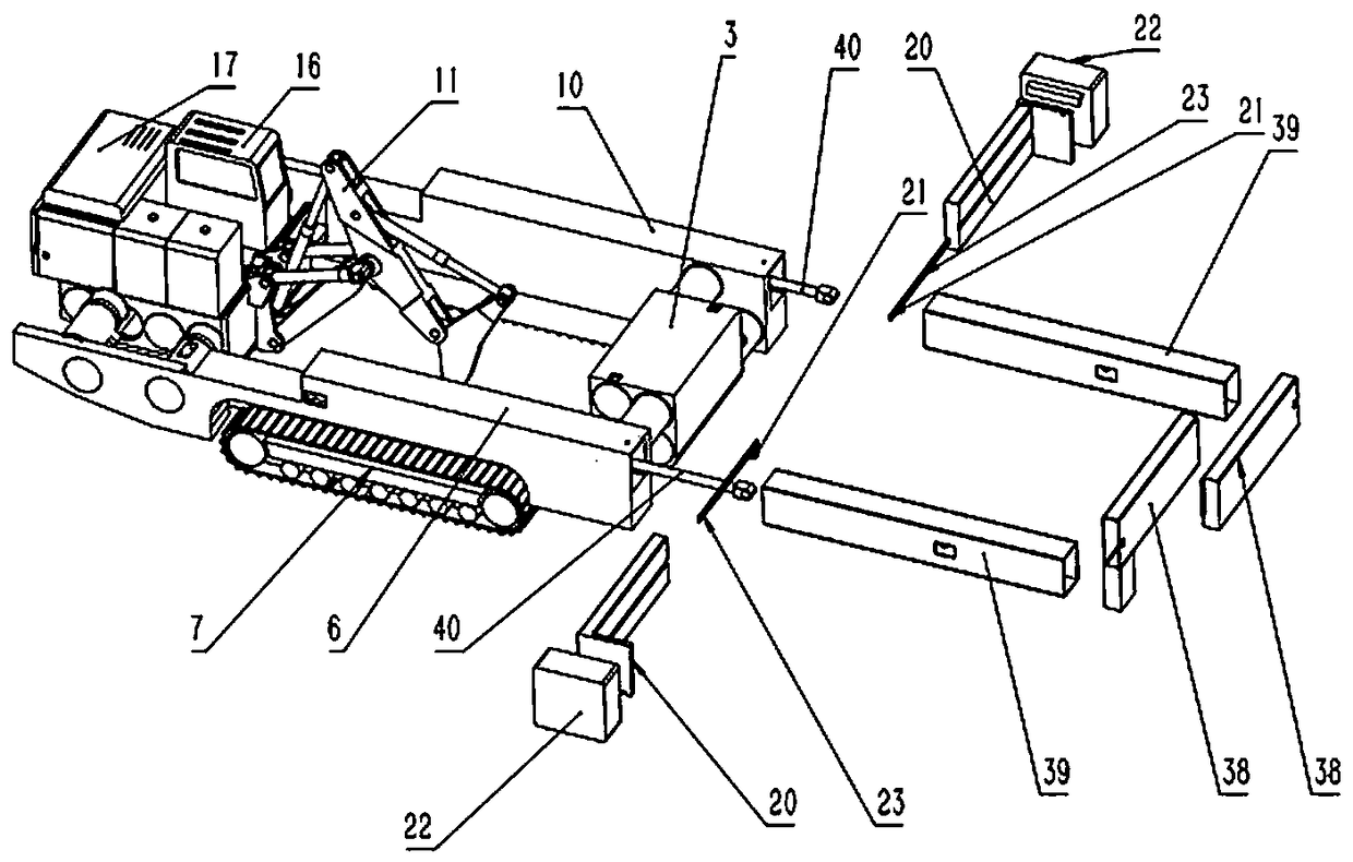
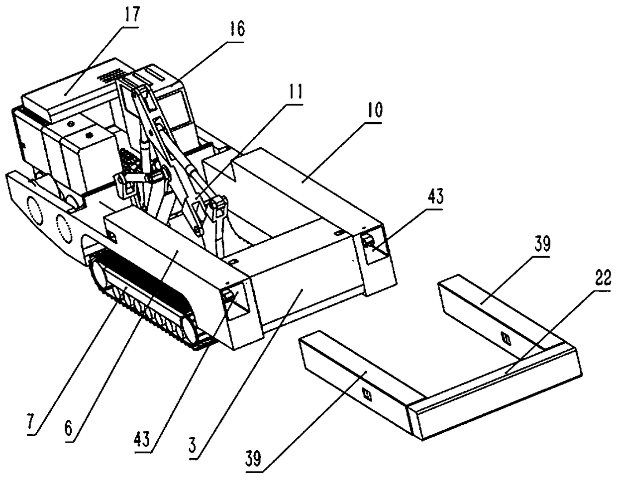
[0028] refer to figure 1 , the rock breaker, including a power part 17, a control room 16, a car body with a hollow area in the up and down direction and a rock arm 11 located in the hollow area, walking 7 is arranged on both sides of the car body, and the rock arm 11 can be equipped with a bucket The ripper with teeth carries out the rock-breaking operation. The side beams 6 and 10 on both sides of the vehicle body are provided with a hollow cavity 43 along the longitudinal direction. , the longitudinal telescopic block 39 is slidingly connected with the cavity, one end of the longitudinal telescopic block 39 is located in the cavity, and the other end is located outside the cavity, the telescopic drive device 40 can drive the longitudinal telescopic block 39 to expand and contract in the cavity, and the longitudinal telescopic block 39 is located at one end outside the cavity to connect There is a counterweight assembly.

[0029] The counterweight assembly comprises a horiz...

Embodiment 2

[0034] refer to Figure 4 , the rock breaker, including a power part 17, a control room 16, a car body with a hollow area in the up and down direction and a rock arm 11 located in the hollow area, walking 7 is arranged on both sides of the car body, and the rock arm 11 can be equipped with a bucket The ripper with teeth carries out the rock-breaking operation. The side beams 6 and 10 on both sides of the vehicle body are provided with a hollow cavity 43 along the longitudinal direction. , the longitudinal telescopic block 39 is slidingly connected with the cavity, one end of the longitudinal telescopic block 39 is located in the cavity, and the other end is located outside the cavity, the telescopic drive device 40 can drive the longitudinal telescopic block 39 to expand and contract in the cavity, and the longitudinal telescopic block 39 is located at one end outside the cavity to connect There is a counterweight assembly.

[0035] The counterweight assembly is a counterweig...

Embodiment 3

[0039] The rock breaker includes a power part 17, a control room 16, a car body with a hollow area in the upper and lower directions, and a rock arm 11 located in the hollow area. Walking 7 is arranged on both sides of the car body, and the rock arm 11 can be equipped with a bucket tooth. The ripper carries out the rock-breaking operation, and the side beams 6 and 10 on both sides of the car body are longitudinally provided with a hollow cavity 43, and the length direction of the walking 7 is longitudinally arranged along the side beams 6 and 10, and a longitudinal telescopic block 39 is arranged in the cavity. The longitudinal telescopic block 39 is slidingly connected to the cavity. One end of the longitudinal telescopic block 39 is located in the cavity, and the other end is located outside the cavity. The telescopic drive device 40 can drive the longitudinal telescopic block 39 to expand and contract in the cavity. Heavy components.

[0040] The counterweight assembly incl...


PUM


Abstract

The invention discloses a rock breaking machine with telescopic side beams. The rock breaking machine with the telescopic side beams comprises a power portion, a control chamber, a vehicle body with ahollow area in the vertical direction and a rock arm located in the hollow area, walking devices are arranged on the two sides of the vehicle body, and the rock arm can carry a scarifier with a bucket gear to conduct rock breaking operation. The rock breaking machine with the telescopic side beams is characterized in that the side beams on the two sides of the vehicle body are provided with hollow cavities in the longitudinal direction, the length directions of the walking devices are arranged in the longitudinal direction of the side beams, longitudinal telescopic blocks are arranged in thecavities and slidably connected with the cavities, one end of each telescopic block is located in the corresponding cavity, the other end of each telescopic block is located outside the correspondingcavity, telescopic driving devices can drive the longitudinal telescopic blocks to telescope in the cavities, and a counterweight assembly is connected to the end, located outside the corresponding cavity, of each longitudinal telescopic block.

Description

technical field [0001] The invention relates to a rock breaker used for breaking rock formations in mines and foundation construction, in particular to a rock breaker with a hollow body. Background technique [0002] In the rock formation breaking construction of mining and foundation construction, rippers are widely used for rock formations that are not too hard due to their high efficiency. The main equipment equipped with rippers are bulldozers and excavators. Can not make full use of the weight of the equipment to obtain larger cutting force, in order to overcome the above technical problems, there have been rock breakers such as publication numbers CN106979010A. The rock breaking operation can be carried out inside, and the weight of the rock breaking machine can be fully utilized to obtain a large cutting force. [0003] Due to its structural characteristics, in order to meet most transportation conditions, the rock breaker takes walking as the dividing point. The are...

Claims


Application Information

Patent Timeline
IPC IPC(8): E21B7/02E21B15/00
CPCE21B7/025E21B15/003E21B15/006
Inventor 凌杰
Owner 四川猎石者龙宇科技有限公司
Learn More