


Quick Research
Generate reliable direction feasibility study reports for your R&D in just a few steps.

Technical Q&A
Discover and master advanced knowledge NOW. Basics, ideas, possibilities, all at once.

Find Solutions
As an expert in R&D theories, this can generate solutions to your technical problems instantly.

Evaluate Feasibility
Analyze your overall solution with one click, know your potential R&D risks in advance.

Monitor Landscape
Get weekly tech updates, stay abreast of the latest tech innovations and key insights.
A heat-dissipating magnetic rotary handle
A rotating handle, heat dissipation technology, applied in steering mechanism, bicycle accessories, transportation and packaging, etc., can solve the problems of rider discomfort, poor handle ventilation, high risk, improve safety and comfort, reduce palm The probability of sweating, the effect of improving the heat dissipation effect
- Summary
- Abstract
- Description
- Claims
- Application Information
AI Technical Summary
Problems solved by technology
Method used
Image

Examples
Embodiment 1
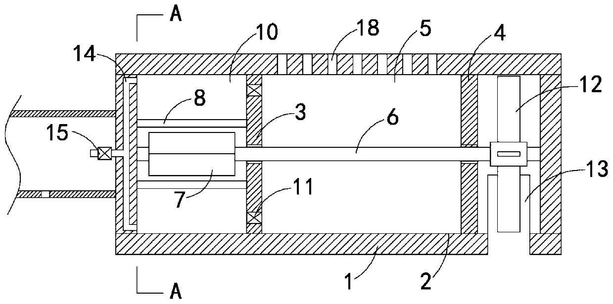
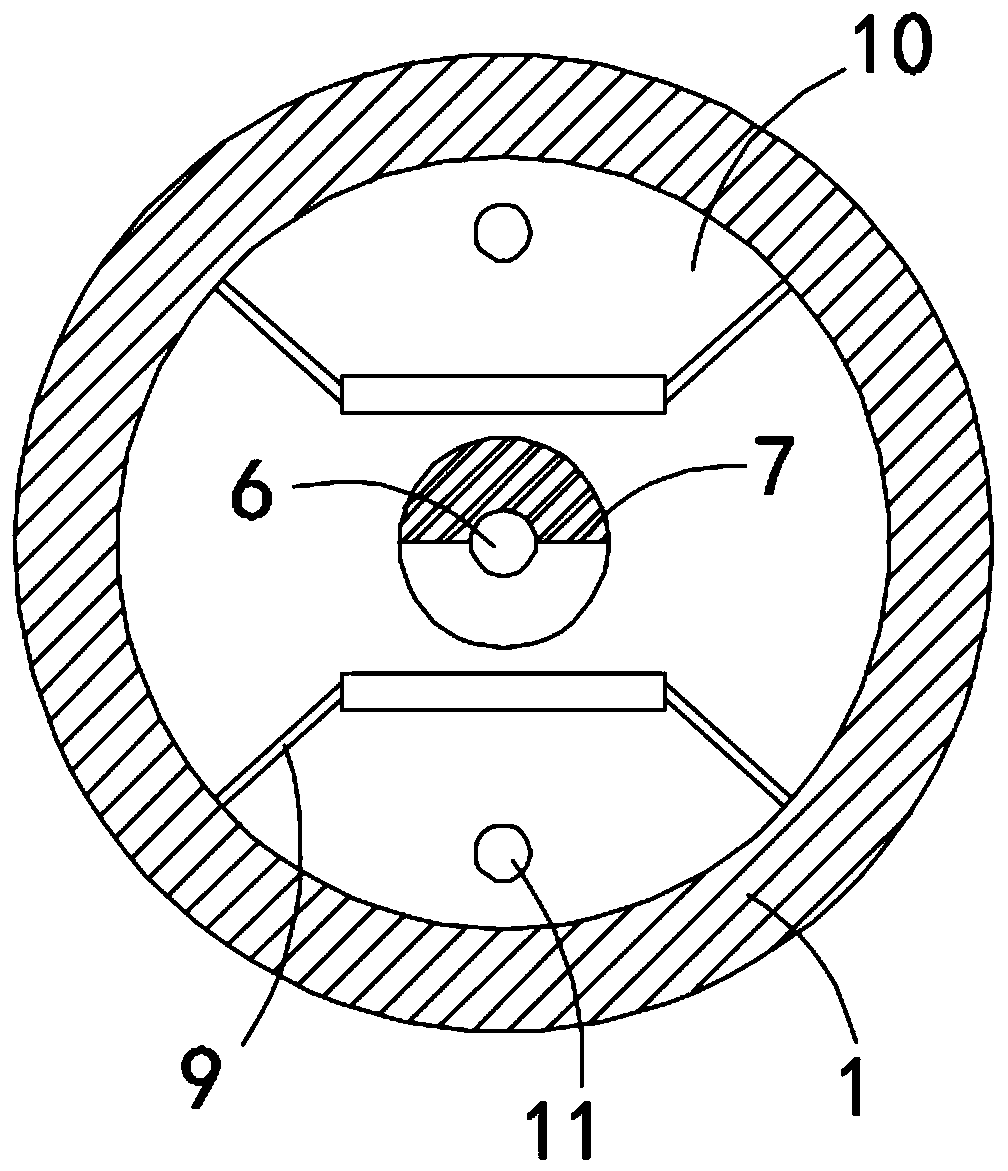
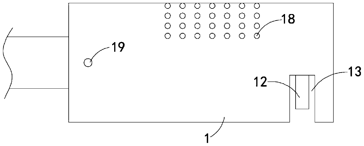
[0018] Such as Figure 1-3 As shown, a heat-dissipating magnetic rotary handle includes a handle body 1, a cavity 2 is provided in the handle body 1, a first fixed plate 3 and a second fixed plate 4 are fixedly connected to the handle body 1 side by side, and the first fixed plate 3 , the second fixed plate 4 and the side walls of the cavity 2 jointly form an air suction chamber 5, the upper surface of the air suction chamber 5 is provided with a plurality of air suction holes 18, and the cavity 2 is rotatably connected with a rotating shaft 6, and the rotating shaft 6 Set through the first fixed plate 3 and the second fixed plate 4, the first fixed plate 3 and the second fixed plate 4 are connected to the rotating shaft 6 in a rotational seal, and the rotating shaft 6 is located on the first fixed plate 3 away from the second fixed plate 4 The part on the side is coaxially fixedly connected with a permanent magnet column 7, the permanent magnet column 7 is made up of two magn...
Embodiment 2
[0023] Such as Figure 4 As shown, the difference between this embodiment and Embodiment 1 is that the exhaust mechanism includes a second exhaust pipe 16 embedded in the side wall of the handle body, and the two input ends of the second exhaust pipe 16 are respectively connected to the two The two exhaust chambers 10 are connected, and the output end of the second exhaust pipe 16 extends to one side of the wind wheel 12 and is set against the fan blade of the wind wheel 12. It should be noted that the output end of the second exhaust pipe 16 The third check valve 17 is fixedly connected to the second exhaust pipe 16 near the leeward side of the wind wheel 12 , and the third check valve 17 allows gas to be exhausted from the exhaust cavity 10 in one direction.
[0024] In this embodiment, when the gas in the exhaust chamber 10 is discharged along the second exhaust pipe 16, the wind wheel 12 can be blown to promote the rotation of the wind wheel 12, reduce energy loss, and imp...
PUM
 Abstract
Description
Claims
Application Information
 - R&D Engineer
- R&D Manager
- IP Professional
- Industry Leading Data Capabilities
- Powerful AI technology
- Patent DNA Extraction
Browse by: Latest US Patents, China's latest patents, Technical Efficacy Thesaurus, Application Domain, Technology Topic, Popular Technical Reports.
© 2024 PatSnap. All rights reserved.Legal|Privacy policy|Modern Slavery Act Transparency Statement|Sitemap|About US| Contact US: help@patsnap.com