Chinese calligraphy brush pen spray washing device and using method thereof
A technology of spray cleaning device and writing brush, which is applied to devices for removing and removing pen tips, printing, writing utensils, etc., can solve the problems of spending a lot of time and energy, low cleaning efficiency, and easy to get dirty water on clothes, etc. , to achieve the effect of keeping clothes clean, saving water resources and improving cleaning efficiency
- Summary
- Abstract
- Description
- Claims
- Application Information
AI Technical Summary
Problems solved by technology
Method used
Image
Examples
no. 1 example
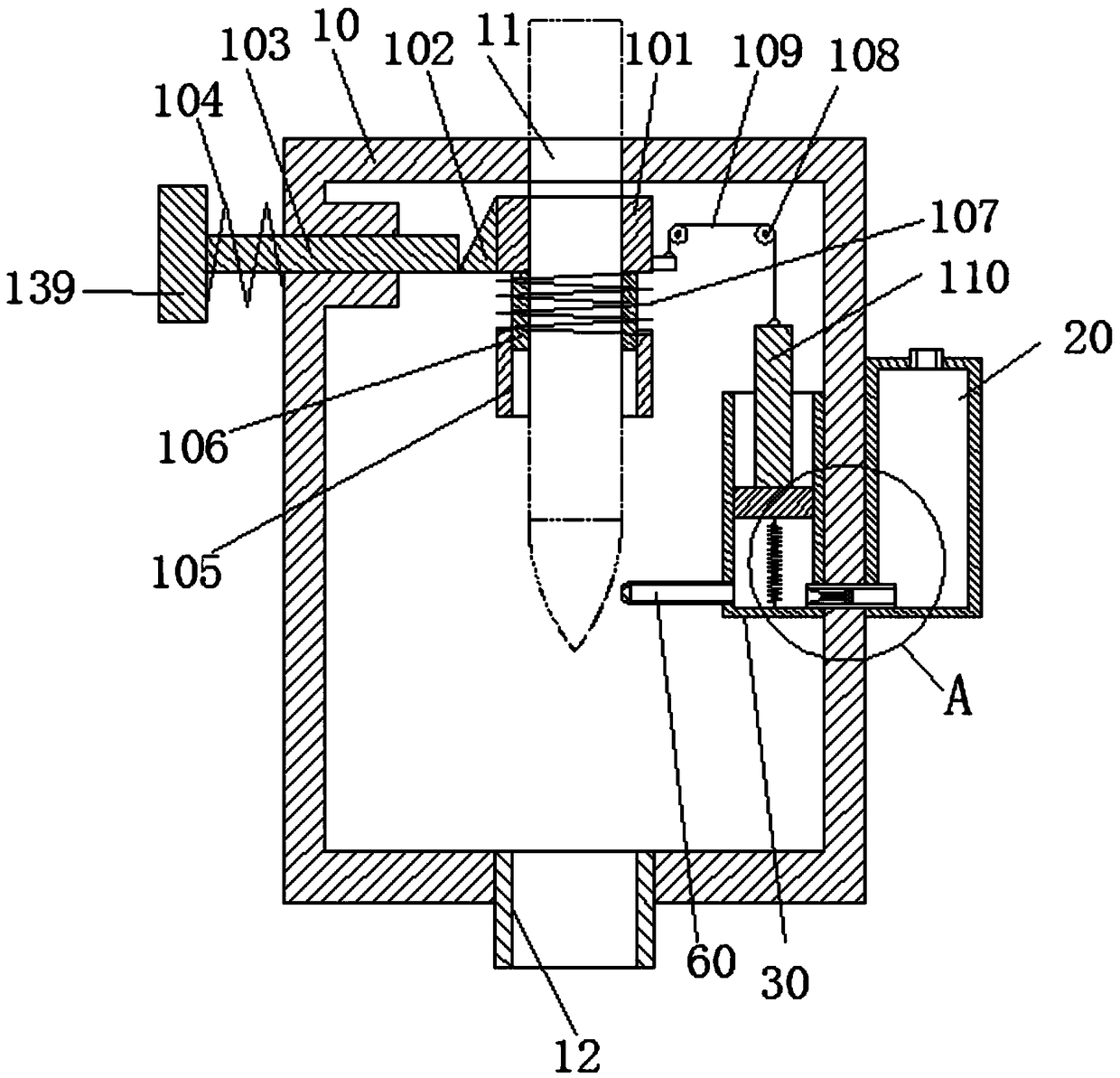
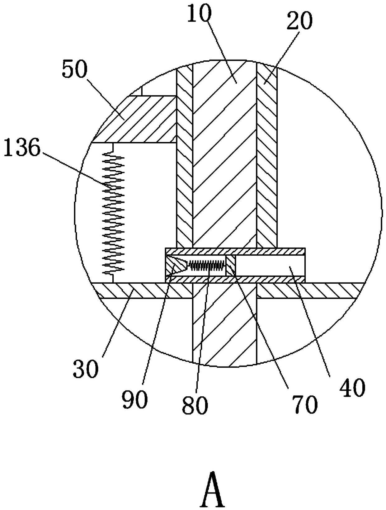
[0081] refer to figure 1 , figure 2 , the first embodiment of the present invention: the drive mechanism 100 includes an elastic clip 101, a wedge block 102, a first pressure rod 103, a first return spring 104, a first support plate 105, a limit bar 106, a spring 107, two A pulley 108, a stay cord 109, a second extension spring 136, an elastic clip 101 that can move up and down is arranged in the housing 10, a wedge-shaped block 102 is fixed on the outer surface of the elastic clip 101, and the first pressing rod 103 is horizontally slidable and arranged in the casing On the side wall of the housing 10, a first button 139 is fixed at one end outside the housing 10, and one end extending into the housing 10 acts on the wedge block 102, so that the elastic clip 101 moves up and down in the housing 10, and the first return spring 104 One end is connected to the first button 139, the other end is connected to the outer wall of the housing 10, and is movably sleeved on the outer ...
no. 2 example
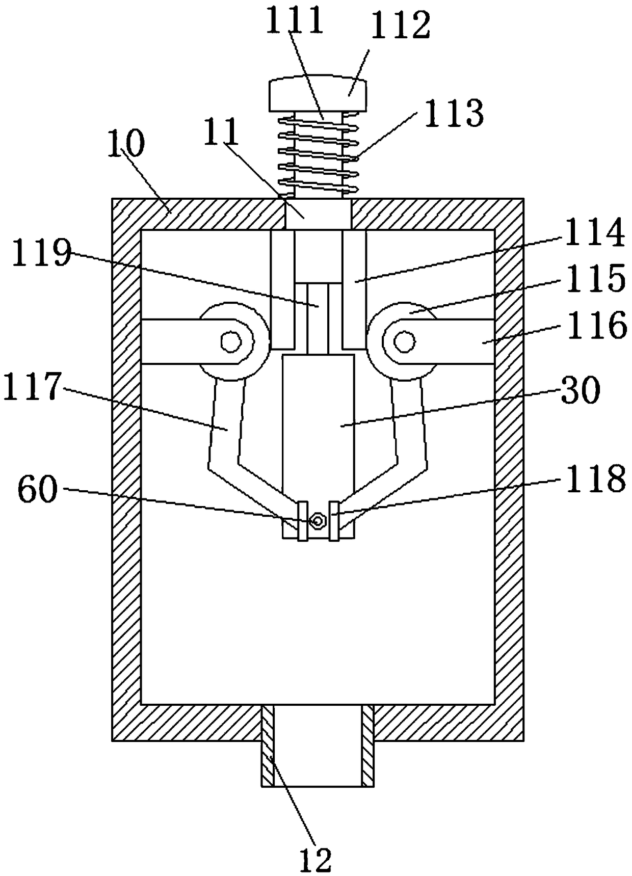
[0082] refer to image 3 , Figure 4 , Figure 5 , the second embodiment of the present invention: the driving mechanism 100 includes a second pressing rod 111, a second return spring 113, two first racks 114, two rotating arms 117, a first connecting rod 119, a second pressing The rod 111 slides up and down on the top wall of the housing 10, one end is located outside the housing 10 and is fixed with a second button 112, the other end extends into the housing 10, one end of the second return spring 113 is fixedly connected with the second button 112, and the other end is fixed to the second button 112. One end is fixedly connected with the top wall of the casing 10, and is movably sleeved on the outer periphery of the second pressure rod 111. Two first racks 114 are respectively fixed on both sides of the second pressure rod 111. The two first racks 114 deviate from One side of the second pressure bar 111 is engaged with the first gear 115 respectively, and the first gear 1...
no. 4 example
[0084] refer to Figure 9 , Figure 10 , Figure 11 , the fourth embodiment of the present invention: the driving mechanism 100 includes a rotating rod 127, an incomplete gear 130, and a second support plate 134. The rotating rod 127 is rotatably arranged on the side wall of the housing 10 through a bearing, and it is located outside the housing 10. A handle 128 is fixed at one end of the handle 128, and a second bevel gear 129 is fixedly connected to one end extending into the housing 10. The incomplete gear 130 is fixed on the shaft of the rotating rod 127, and the surface of the incomplete gear 130 is meshed with a frame rack 131. , the lower surface of the frame rack 131 is fixed with a piston rod 132, the two sides of the piston rod 132 are provided with a limiting plate 133 that limits the sliding of the piston rod 132, the limiting plate 133 is fixed on the inner wall of the housing 10, and the piston rod 132 The bottom is fixedly connected with the piston 50, and the...
PUM
 Abstract
Description
Claims
Application Information
 - R&D Engineer
- R&D Manager
- IP Professional
- Industry Leading Data Capabilities
- Powerful AI technology
- Patent DNA Extraction
Browse by: Latest US Patents, China's latest patents, Technical Efficacy Thesaurus, Application Domain, Technology Topic, Popular Technical Reports.
© 2024 PatSnap. All rights reserved.Legal|Privacy policy|Modern Slavery Act Transparency Statement|Sitemap|About US| Contact US: help@patsnap.com


