Automatic assembly equipment for radiator fan

A technology for automatic assembly and cooling fans, applied in assembly machines, metal processing equipment, metal processing, etc., can solve the problems affecting the efficiency of computer operation, computer life, defective cooling fan assembly, waste of time in turnover and testing, etc. Fast assembly speed, reduced labor costs, and the effect of reducing transshipment links

Inactive Publication Date: 2019-02-22
深圳市阿尓法智慧科技有限公司
View PDF2 Cites 8 Cited by
  • Summary
  • Abstract
  • Description
  • Claims
  • Application Information

AI Technical Summary

Problems solved by technology

[0002] With the acceleration of people's life rhythm and the development of information technology transmission, computers have become an indispensable and important tool in people's work and life. They need computers when they are working, and they also need computers when they return home. Business negotiations are also inseparable. The use of computers and the rapid development of notebook computers have occupied most of the market for computer usage. At the same time, various brands of computers have entered people's lives, which has a certain impact on the quality and efficiency of computer production. Requirements, the conventional single assembly line production can no longer meet the production needs, the turnover and inspection of each process waste a lot of time, but also increase the cost, reduce the efficiency, and cannot meet the existing needs; therefore, the existing production technology exists Certain defects require large-scale, automated, and intelligent production. As an integral part of notebook computers, automatic assembly of cooling fans is urgently needed;
[0003] In the production process, the automation of the entire production is a collection of multiple automated assembly lines, and the reassembly between multiple assemblies forms a complete whole. In the collection of automated assembly lines, the assembly of cooling fans is a relatively An indispensable assembly line, the quality of the cooling fan also directly affects the efficiency of the computer's work and operation and the life of the computer. The assembly of the existing cooling fan is defective to meet production requirements

Method used


Image

  • Automatic assembly equipment for radiator fan
  • Automatic assembly equipment for radiator fan
  • Automatic assembly equipment for radiator fan

Examples


Embodiment Construction

[0041] In order to facilitate the understanding of the present invention, the present invention will be described in more detail below with reference to the drawings and specific embodiments. The drawings show preferred embodiments of the present invention. However, the present invention can be implemented in many different forms and is not limited to the embodiments described in this specification. On the contrary, the purpose of providing these embodiments is to make the understanding of the disclosure of the present invention more thorough and comprehensive.

[0042] It should be noted that when an element is referred to as being "fixed to" another element, it may be directly on the other element or a central element may also exist. When an element is considered to be "connected" to another element, it can be directly connected to the other element or an intermediate element may be present at the same time. The terms "fixed", "integrated", "left", "right" and similar express...


PUM


Abstract

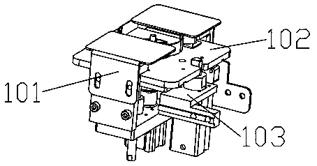
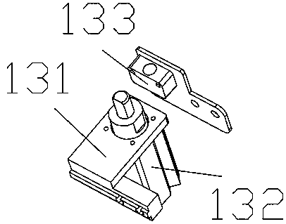
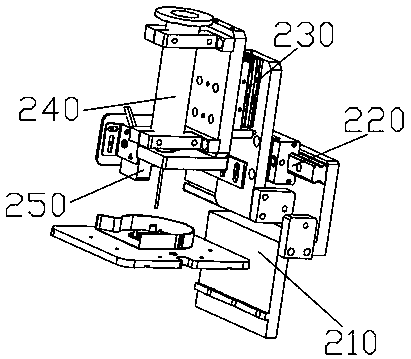
The invention discloses automatic assembly equipment for a radiator fan. The automatic assembly equipment comprises a supporting cabinet body, an intelligent control terminal, an electrical appliancecontrol cabinet and a protective housing. The automatic assembly equipment is characterized by further comprising a conveying device, wherein an upper friction plate, an upper locking ring, a dispensing device, an annular shaft installer, a motor loading installer, a pressing device, a rotary piston ring installer, and an impeller installer are sequentially arranged on the conveying device; and anarray take-place device is mounted at the side of the impeller installer, so that assembly of the radiator fan is realized, and therefore, assembly in the whole process is completed. The automatic assembly equipment realizes automatic assembly for the radiator fan, reduces the transfer link in an assembly production process, enables the production process to be centralized, is quick in assembly,is intelligent in operation, greatly improves production efficiency, and reduces labour cost.

Description

Technical field [0001] The invention relates to a device assembling equipment for a notebook computer, in particular to an automatic cooling fan machine. Background technique [0002] With the accelerating pace of people’s lives and the development of information technology transmission, computers have become an indispensable tool in people’s work and life. They need computers for working hours and computers when they return home. Business negotiations are also inseparable. The use of computers, and the rapid development of notebook computers at the same time, occupy most of the market for computer usage. At the same time, a variety of brand computers have entered people’s lives and have a certain degree of quality and efficiency in computer production. Requirements, the conventional single-line production can no longer meet the production needs, the turnover and inspection of each process waste a lot of time, but also increase the cost, reduce the efficiency, and cannot meet the...

Claims


Application Information

Patent Timeline
Patent Type & Authority Applications(China)
IPC IPC(8): B23P21/00
CPCB23P21/004B23P19/001B23P19/004B23P19/007
Inventor 潘亚军
Owner 深圳市阿尓法智慧科技有限公司
Why Eureka
Try Eureka