
Puncher pin auxiliary device suitable for self-piercing riveting and self-piercing riveting method

An auxiliary device, self-piercing riveting technology, applied in the field of basically no cutting or processing of bars or profiles, metal plates or tubes, it can solve the problems of poor mechanical properties of joints, difficult metal forming, and high welding temperature, so as to improve the quality, Simple structure and strong operability

Pending Publication Date: 2019-02-22
杭州捷能科技有限公司
View PDF0 Cites 4 Cited by
  • Summary
  • Abstract
  • Description
  • Claims
  • Application Information

AI Technical Summary

Problems solved by technology

[0006] The invention solves the problems of poor weldability, high welding temperature and poor welding quality in resistance spot welding in connection of dissimilar materials in the prior art, while self-piercing riveting is suitable for materials with poor plasticity and high strength, such as magnesium alloy, High-strength steel is easy to cause metal cracking, and there are defects such as large riveting force, difficult metal forming, and poor mechanical properties of joints. The present invention provides an optimized punch auxiliary device and self-piercing riveting method suitable for self-piercing riveting

Method used


Image

  • Puncher pin auxiliary device suitable for self-piercing riveting and self-piercing riveting method
  • Puncher pin auxiliary device suitable for self-piercing riveting and self-piercing riveting method
  • Puncher pin auxiliary device suitable for self-piercing riveting and self-piercing riveting method

Examples


Embodiment Construction

[0041] The present invention will be described in further detail below in conjunction with the examples, but the protection scope of the present invention is not limited thereto.

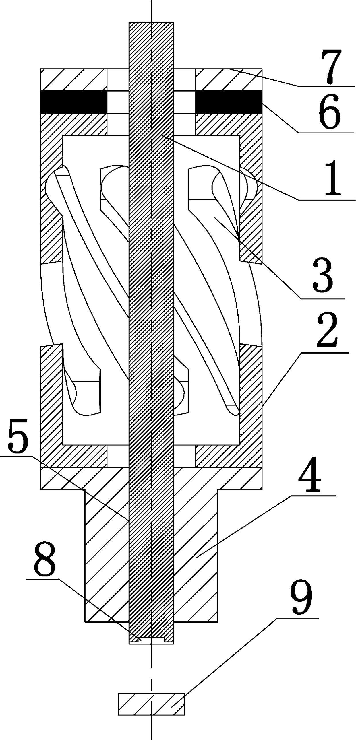
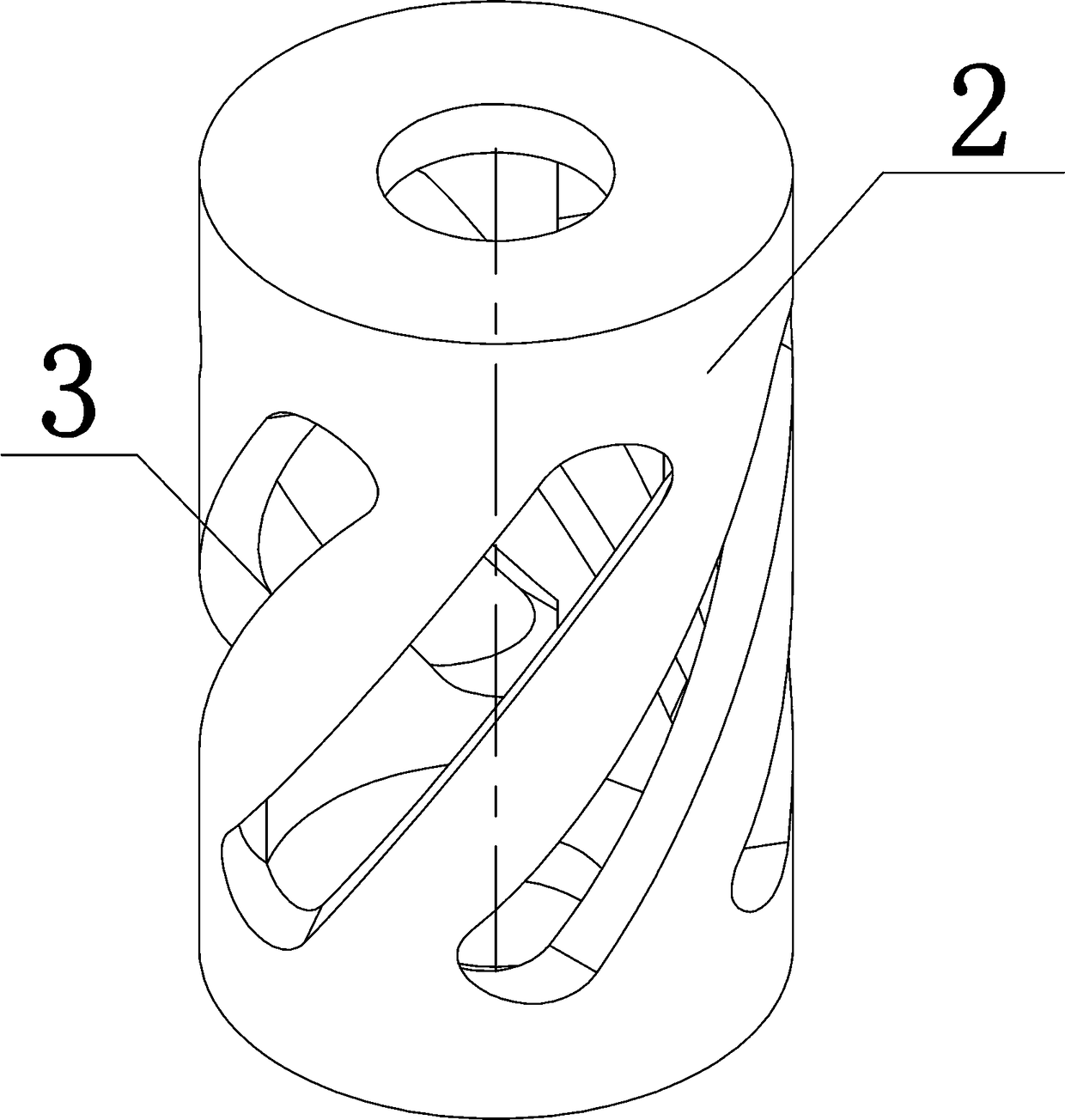
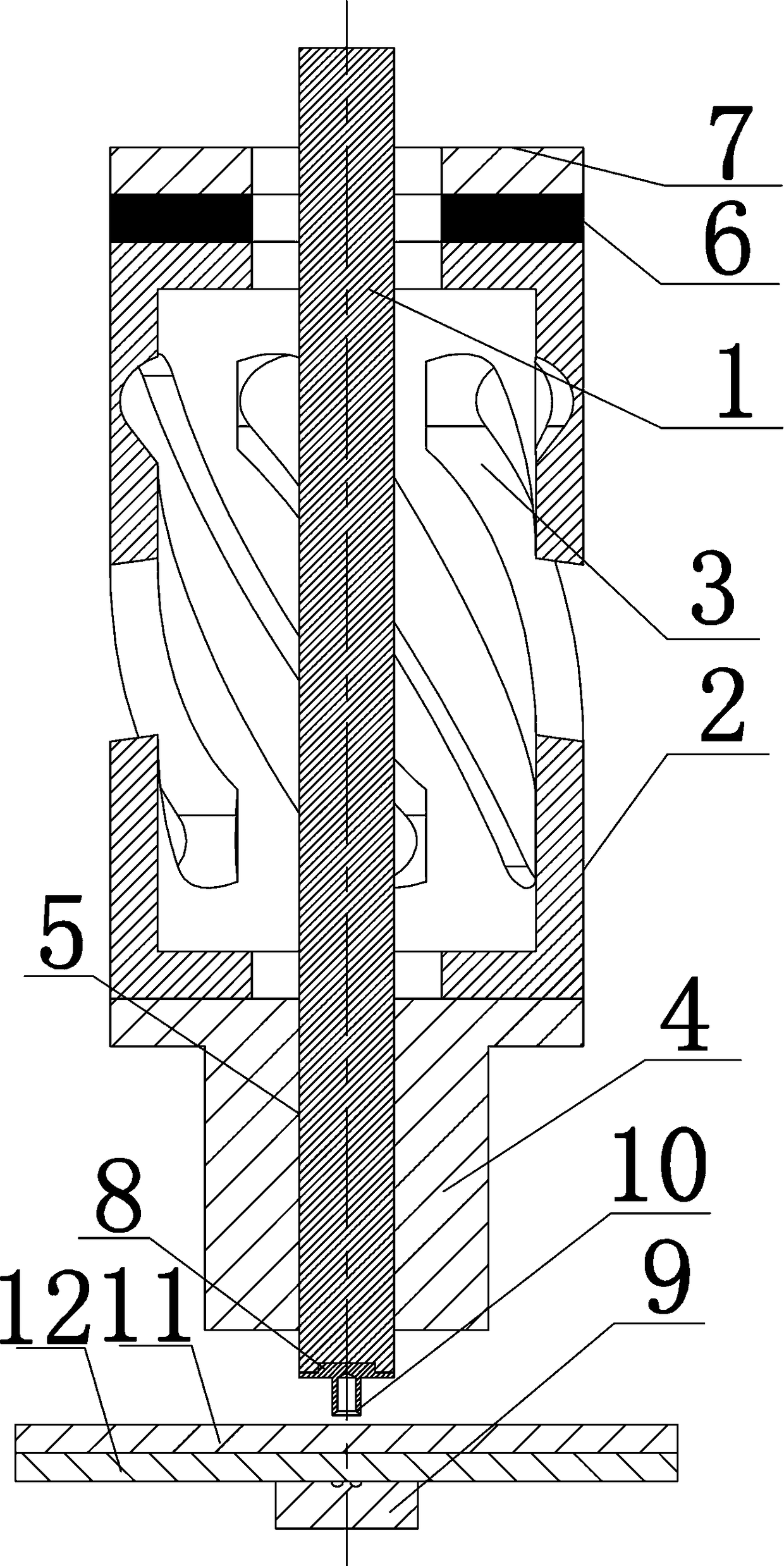
[0042] The invention relates to a punch auxiliary device suitable for self-piercing riveting. The punch auxiliary device is sleeved on the outside of the punch 1. The punch auxiliary device includes a hollow luffing mechanism, and the luffing mechanism cooperates with a There is a driving mechanism, and the amplitude-changing mechanism is screwed with the punch 1 .

[0043] In the present invention, the punch auxiliary device is sleeved on the outside of the punch 1. As a vibration aid for the punch 1, the driving mechanism drives the hollow luffing mechanism to perform the luffing vibration, and transmits the vibration of the luffing mechanism to the punch 1. Vibration assistance for the SPR process.

[0044] In the present invention, the luffing mechanism is threadedly connected with the punch 1,...


PUM


Abstract

The invention relates to a puncher pin auxiliary device suitable for self-piercing riveting and a self-piercing riveting method. The puncher pin auxiliary device is arranged on the outer side of a puncher pin in a sleeving manner, a hollow amplitude variation mechanism of the puncher pin auxiliary device is driven by a drive mechanism for amplitude variation vibration, and vibration of the amplitude variation mechanism is transmitted to the puncher pin in threaded connection with the amplitude variation mechanism for vibration assistance. In the puncher pin auxiliary device, vibration is transmitted to to-be-connected parts through rivets, and the to-be-connected parts are promoted to be in full contact; metal plates are prevented from cracking, and the pressure needed for riveting is reduced; equipment light weight operation is promoted, the rivets, the plates and concave dies are promoted to be in full contact, the riveting quality is improved, connecting reliability is improved, andstacking can be achieved on traditional self-piercing riveting equipment; and the advantages that the structure is simple, and operability is high are achieved. On the basis of the traditional SPR process, longitrorse composite vibration with controllable amplitude is added for assisting in stimulation, the application range of the SPR process is widened, and connecting reliability between the to-be-connected parts is improved; and the structure is simple, operability is high, the manufacturing process is improved, and the quality of finished products is improved.

Description

technical field [0001] The present invention relates to the substantially non-cutting processing or processing of metal plates or tubes, rods or profiles; the technical field of stamping, in particular to a punch auxiliary device and self-piercing riveting for vibration assistance in the process of self-piercing riveting Punch riveting method. Background technique [0002] At present, with the support of the state and the favorable market conditions, the power lithium battery industry is developing very rapidly, and its application has been extended to the fields of electric buses, electric cars, micro-buses and energy storage. [0003] The main joining methods currently used in body assembly in the automotive industry are resistance spot welding and self-piercing riveting. [0004] Resistance spot welding has an irreplaceable advantage in welding the traditional steel body made of a single material, and has been successfully applied on a large scale in the industry for dec...

Claims


Application Information

Patent Timeline
IPC IPC(8): B21J15/02B21J15/38
CPCB21J15/025B21J15/38
Inventor 占伟涛刘勇程国阳
Owner 杭州捷能科技有限公司
Learn More