
A side groove geometry optimization design method for compact tensile specimens with side grooves

A technology of compact stretching and geometric optimization, which is applied in the field of geometric optimization design of side grooves, can solve problems such as inability to ensure the consistency of crack front fracture parameter distribution, and achieve the effects of ensuring consistency, ensuring straightness, and improving accuracy

Active Publication Date: 2020-06-16
NANJING UNIV OF AERONAUTICS & ASTRONAUTICS
View PDF7 Cites 0 Cited by
  • Summary
  • Abstract
  • Description
  • Claims
  • Application Information

AI Technical Summary

Problems solved by technology

Literature research shows that using the V-shaped side groove suggested by the standard does not guarantee the consistency of the fracture parameter distribution of the crack front

Method used


Image

  • A side groove geometry optimization design method for compact tensile specimens with side grooves
  • A side groove geometry optimization design method for compact tensile specimens with side grooves
  • A side groove geometry optimization design method for compact tensile specimens with side grooves

Examples


Embodiment

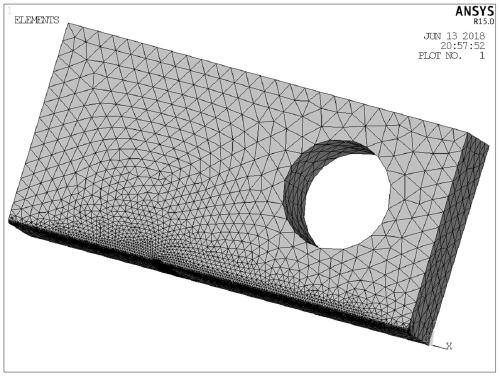
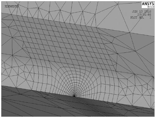
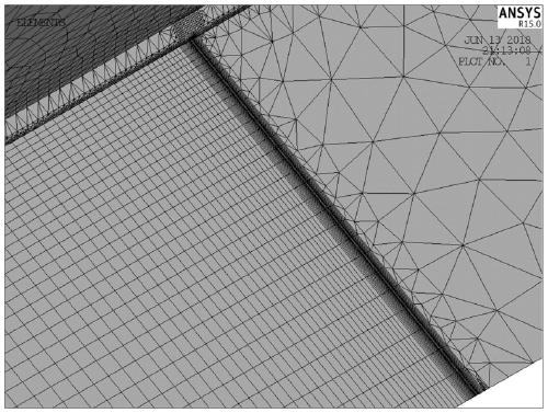
[0052] A side groove geometric optimization design method for a compact tensile test piece with a side groove according to the present invention takes a CT specimen with a side groove with a thickness of 10 mm as an example to further illustrate the side groove optimization process, including the following steps:

[0053] (1) Define the properties of the material used in the tensile test piece in the finite element software, query the material booklet, use FGH96's elastic modulus E=214000MPa, Poisson's ratio u=0.28, and input it to the finite element through command flow or GUI in the software. Aeroengine powder alloy turbine disks are all nickel-based superalloys, and the fracture control parameter is the stress intensity factor K. At the same time, the potential defects and inclusions of powder alloy turbine disks also require damage tolerance design. Therefore, the selection of material properties of FGH96 is typical.

[0054] (2) In the finite element software, the 3-dime...


PUM


Abstract

A side groove geometry design method of a compact tensile specimen with side grooves includes: defining material properties in finite element software; performing 3-D finite element partition; imposing constraints and loads on the finite element model; setting up stress intensity factor calculation; performing solving to obtain finite element results; extracting stress intensity factors and node coordinates of each node at the crack tip of the finite element model and generating the output file; generating batch files; importing the output files of stress intensity factor and node coordinatesinto the data processing software, and calculating and generating the files; importing the batch processing command flow, the output file and the calculation result file into the optimization software; setting variables, constraints and optimization goals; obtaining the final optimization parameters by optimization calculation. As that optimization software is adopted for automatically optimizingthe geometric parameter of the side groove, the invention can obtain more accurate optimal side groove shape more efficiently and quickly, and ensure the consistency of stress intensity factors at thecrack front.

Description

technical field [0001] The invention belongs to the technical field of material testing methods, and in particular relates to a side groove geometric optimization design method for a compact tensile test piece with side grooves. Background technique [0002] The damage tolerance design concept of aeroengine discs is to ensure the service life of the discs based on the actual loading conditions and the crack growth rate of the material under the assumption that there are defects originating from the material or processing. Therefore, one of the key issues in damage tolerance design is to establish a reliable crack growth model based on accurate crack growth rate data, and on this basis, accurately predict the life from initial defect to crack growth to disk instability and rupture. [0003] The research on the crack growth behavior and model of metal materials is usually based on the crack growth test of material standard CT specimens. For the crack growth test of standard C...

Claims


Application Information

Patent Timeline
Patent Type & Authority Patents(China)
IPC IPC(8): G06F30/20
CPCG06F30/23
Inventor 胡绪腾张冬阁宋迎东贾旭叶文明
Owner NANJING UNIV OF AERONAUTICS & ASTRONAUTICS
Learn More