
Vertical tower liquid trap of novel structure

A new type of structure, the technology of the tower liquid collector, applied in the direction of steam condensation, chemical instruments and methods, steam/steam condensers, etc., can solve the problems of reduced liquefaction effect, low gas-liquid separation, high input cost, etc., and achieves a simple structure. ,Easy to operate and save material effect

Pending Publication Date: 2019-02-19
BEIJING GUODIAN LONGYUAN ENVIRONMENTAL ENG
View PDF0 Cites 5 Cited by
  • Summary
  • Abstract
  • Description
  • Claims
  • Application Information

AI Technical Summary

Problems solved by technology

[0003] However, in the existing vertical tower liquid collector, the water collecting tank and the gas-lifting cap need to be placed on an additional supporting beam, and the input cost is large, and the existing vertical tower liquid collector has low gas-liquid separation, and some water vapor is convenient It flows with the flow of gas, which reduces the liquefaction effect and the use effect is low. Therefore, a vertical tower liquid collector with a new structure is needed to solve the above problems

Method used


Image

  • Vertical tower liquid trap of novel structure
  • Vertical tower liquid trap of novel structure
  • Vertical tower liquid trap of novel structure

Examples


Embodiment Construction

[0020] Before describing the embodiments in detail, it should be understood that the present invention is not limited to the detailed structures or arrangements of elements described herein below or in the accompanying drawings. The present invention can be implemented in other ways. Also, it should be understood that the phraseology and terminology used herein are for descriptive purposes only and should not be interpreted as limiting. The terms "including", "comprising", "having" and similar expressions used herein are meant to include the items listed thereafter, their equivalents and other additional items. In particular, when "a certain element" is described, the present invention does not limit the number of the element to one, but may also include a plurality.

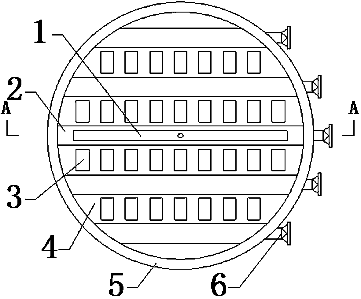
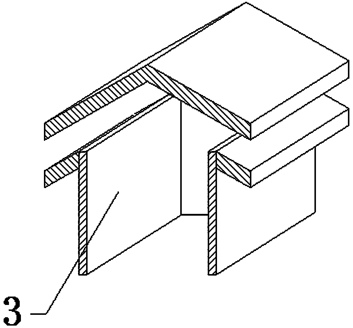
[0021] see Figure 1-Figure 4 , the present invention provides a technical solution: a vertical tower liquid collector with a new structure, including a fixed ring plate 5, the inner side of the fixed ring pla...


PUM


Abstract

The invention provides a vertical tower liquid trap of a novel structure. The vertical tower liquid trap comprises a fixing ring plate. Water collecting tank plates are transversely welded and fixed into the fixing ring plate, fixing skins are welded to the front ends of the water collecting tank plates, gas rising caps are fixed to the front ends of the skins, the rear ends of the gas rising capsstretch out of the rear ends of the skins, connecting pipes are fixed to the right end of the annular side face of the fixing ring plate, and the left sides of the connecting pipes penetrate throughthe fixing ring plate and communicate with the water collecting tank plates. According to the design, the number of the water collecting tank plates is increased, the skins and the gas rising caps aresupported by the water collecting tank plates, use of supporting beams is reduced, materials are saved, and the flow area of gas is increased.

Description

technical field [0001] The invention is a vertical tower liquid collector with a novel structure, which belongs to the field of liquid collector equipment. Background technique [0002] Various types of spray towers often have multiple layers of spraying for different purposes. In order not to affect each other between the spraying layers, a gas-liquid separation device, that is, a liquid collector, needs to be installed in the tower. A liquid trap often includes a sump and a lift cap. [0003] However, in the existing vertical tower liquid collector, the water collecting tank and the gas-lifting cap need to be placed on an additional supporting beam, and the input cost is large, and the existing vertical tower liquid collector has low gas-liquid separation, and some water vapor is convenient It flows with the flow of the gas, thereby reducing the liquefaction effect, and the use effect is low. Therefore, a vertical tower liquid collector with a new structure is needed to ...

Claims


Application Information

Patent Timeline
IPC IPC(8): F28B9/08B01D5/00B01D53/00
CPCB01D5/00B01D53/00F28B9/08
Inventor 陈建邹文杰钟洪玲劳俊李晓金王丹闫雷
Owner BEIJING GUODIAN LONGYUAN ENVIRONMENTAL ENG
Learn More