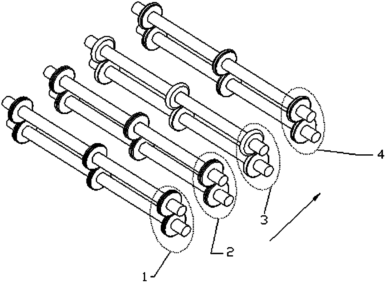
Cardboard crimping device and cardboard manufacturing device and stapler with crimping device
A crimping device and cardboard technology, applied in container manufacturing machinery, rigid/semi-rigid container manufacturing, paper/cardboard containers, etc., can solve problems such as increased input costs, unfavorable integrated production, irreplaceable or cancelled process procedures, etc.
- Summary
- Abstract
- Description
- Claims
- Application Information
AI Technical Summary
Problems solved by technology
Method used
Image
Examples
Embodiment 1
[0046] Example 1 A set of pre-crimping rollers for outer marks
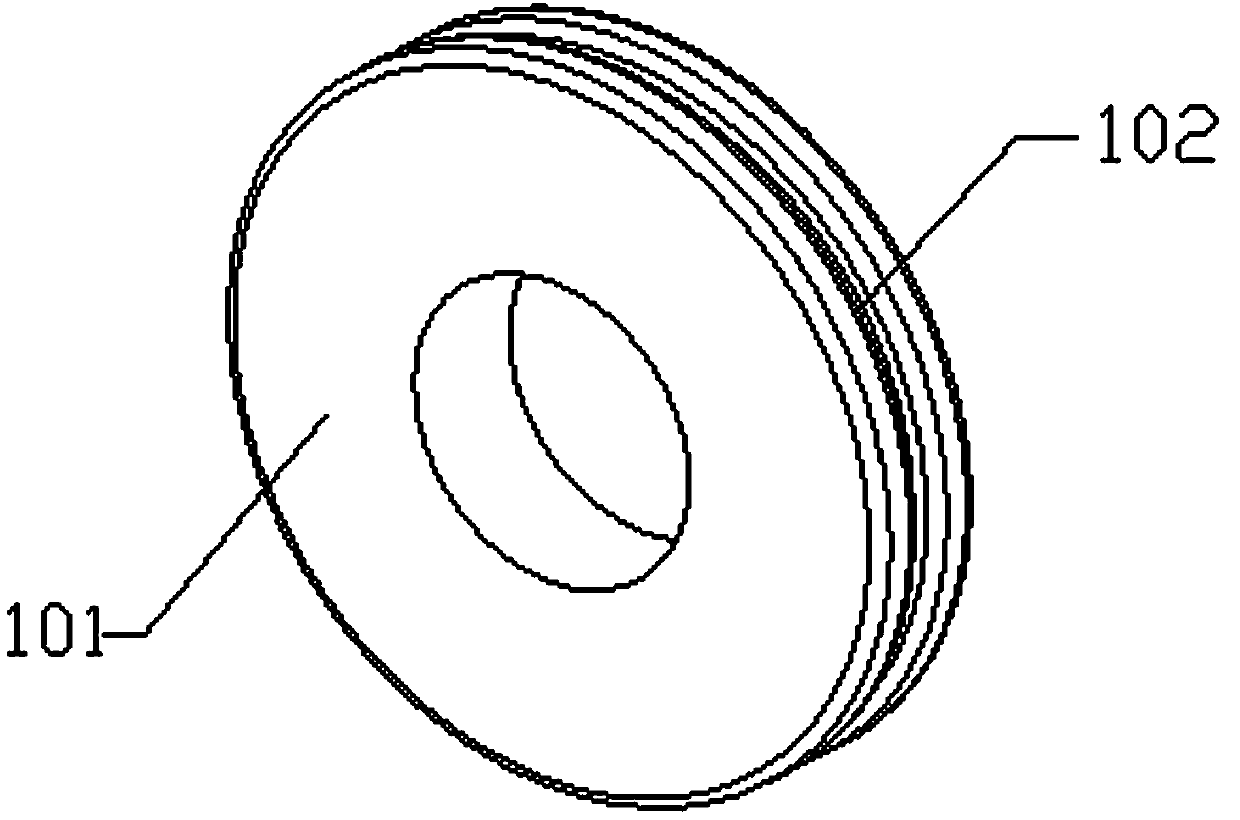
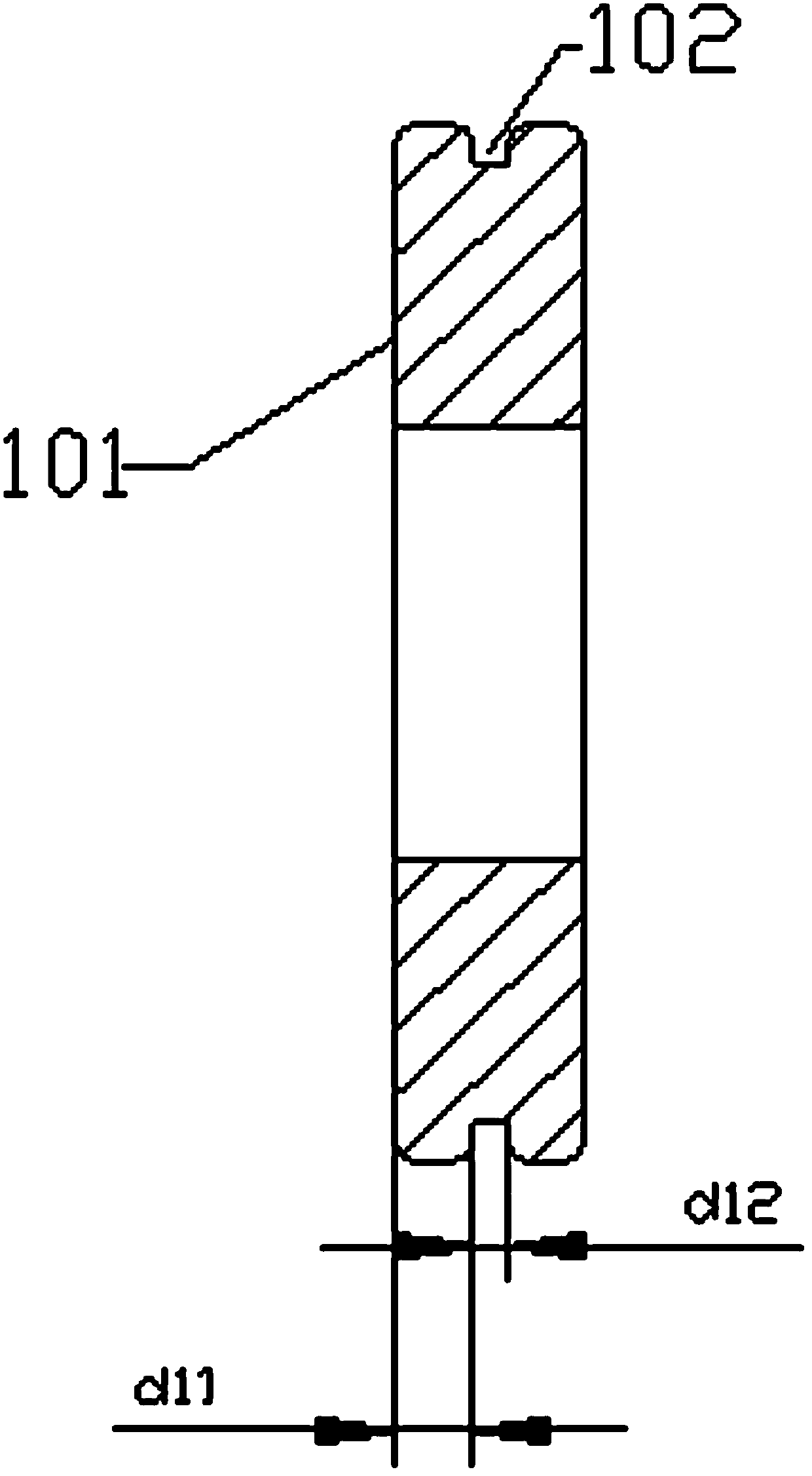
[0047] This embodiment discloses a set of pre-crimping rollers for outer marks, such as figure 2 , image 3 As shown, it includes two outer creasing rollers 101, the two outer creasing rollers 101 are arranged correspondingly, and are respectively coaxially fixed on two first rotating shafts arranged in parallel, the two outer creasing rollers There is a gap between the rollers 101 which is smaller than the thickness of the cardboard. In this embodiment, in order to facilitate the cardboard to enter the gap between the two outer-marking pre-crisp rollers 101, the two outer-mark pre-criminating rollers 101 are arranged up and down. On the circumferential surface of each outer creasing roll 101, an annular first groove 102 recessed inward along the radial direction of the outer creasing roll 101 is formed, and the outer creasing roll 101 is axially two The distance d11 from the end surface of the end to the fir...
Embodiment 2
[0048] Example 2 A set of creasing rolls for outer marking
[0049] This embodiment discloses an outer-marking creasing roller set, which is installed at the cardboard outlet of the outer-marking pre-creasing roller set 1 described in Embodiment 1.
[0050] Such as Figure 4 , Figure 5 As shown, the outer creasing roller group 2 has two outer creasing rollers 201, and the two outer creasing rollers 201 are arranged correspondingly, and are coaxially fixedly installed on two second rotating shafts arranged in parallel; The axes of the second rotating shafts are parallel to the axes of the two first rotating shafts, and the lower first rotating shaft and the second rotating shaft are located on the same horizontal plane, and the upper first rotating shaft and the second rotating shaft are located on the same horizontal plane. In this embodiment, in order to make the outer creasing roller 201 roll on the two pre-creasings, the axial thickness of the outer creasing roller 201 i...
Embodiment 3
[0051] Example 3 A set of creasing rollers in the track
[0052] This embodiment discloses an inner creasing roller set, which is used in conjunction with embodiment 1 and embodiment 2, and is installed at the cardboard outlet of the outer creasing roller set 2 described in embodiment 2.
[0053] Such as Figure 6 , Figure 8 As shown, the creasing roller group 3 in the mark includes a first creasing roller 301 and a second creasing roller 302, and the first creasing roller 301 and the second creasing roller 302 are arranged correspondingly. They are coaxially and fixedly installed on two third rotating shafts arranged in parallel; the axes of the two third rotating shafts are respectively parallel to the axes of the two first rotating shafts and the two second rotating shafts, and are located below the first rotating shaft and the second rotating shaft It is located on the same horizontal plane as the third rotating shaft, and the first rotating shaft above, the second rota...
PUM
 Abstract
Description
Claims
Application Information
 - R&D
- Intellectual Property
- Life Sciences
- Materials
- Tech Scout
- Unparalleled Data Quality
- Higher Quality Content
- 60% Fewer Hallucinations
Browse by: Latest US Patents, China's latest patents, Technical Efficacy Thesaurus, Application Domain, Technology Topic, Popular Technical Reports.
© 2025 PatSnap. All rights reserved.Legal|Privacy policy|Modern Slavery Act Transparency Statement|Sitemap|About US| Contact US: help@patsnap.com


