Al technical title is built by PatSnap Al team. It summarizes the technical point description of the patent document.
A workpiece edge and grinding machine technology, applied in the direction of machine tools suitable for grinding workpiece edges, grinding machine parts, grinding/polishing equipment, etc., can solve the problem of difficult collection and cleaning, affecting workpiece grinding quality and safety Not advanced question
Inactive Publication Date: 2019-02-19
济南市坤鹏技术开发中心
View PDF7 Cites 4 Cited by
Summary
Abstract
Description
Claims
Application Information
AI Technical Summary
This helps you quickly interpret patents by identifying the three key elements:
Problems solved by technology
Method used
Benefits of technology
Problems solved by technology
[0012] The present invention provides an automatic grinding machine for the edge of a workpiece through improvement. During the grinding work, the infrared sensor scans and detects the bottom of the machine head. When the human body is detected, a signal is sent to the single-chip microcomputer to make it turn on the breaker for work. After it works, disconnect the circuit of the third motor, so that the grinding tool stops rotating, and at the same time, the single-chip microcomputer turns on the alarm to work, and sends out an audible and visual alarm to warn, thus solving the problem that the human body accidentally touches the grinding tool when the machine is running Afterwards, safety accidents are prone to occur, and the safety is not high; when the workpiece is being ground, the air compressor pump is turned on, and the gas in the gas storage box is pumped out and pressurized, and then transported to the spray nozzle by the gas pipeline. At the air pipe, it is sprayed from the nozzle at the bottom to the contact between the grinding tool and the workpiece, and the waste chips on the surface are blown to the waste chip inlet and fall, and then collected by the collection tube, thus solving the problem of grinding the workpiece. A large amount of waste will be generated, which is not easy to collect and clean, and adheres to the workpiece, which affects the grinding quality of the workpiece; when changing the workpiece, turn on the fourth motor to drive the screw to rotate, and its slide plate is threaded with the screw. And it is slidingly connected with the slide rail, so that the slide plate moves to the front of the fixed part, and the clamper is transported to the outside, which changes the original equipment and requires the staff to replace the workpiece inside the machine, which is inconvenient to install and prone to safety accidents , which makes it more convenient to replace the workpiece and increases the speed of workpiece replacement, improving safety and work efficiency; after the workpiece is clamped and fixed, the appropriate angle of the workpiece can be adjusted, first turn to loosen the locking bolt, and then turn the adjustment plate to drive The clamper adjusts the left and right angles, so that the angle of the workpiece can be adjusted left and right, and the pointer points to the scale number, which can quickly understand the angle of the workpiece adjustment, thus solving the problem that after the workpiece is clamped and fixed, the left and right angles cannot be changed, and the flexibility is insufficient. The problem of low work efficiency, increased flexibility and work efficiency
Method used
Image
Click on the blue label to locate the original text in one second.
Reading with bidirectional positioning of images and text.
Examples
Embodiment Construction
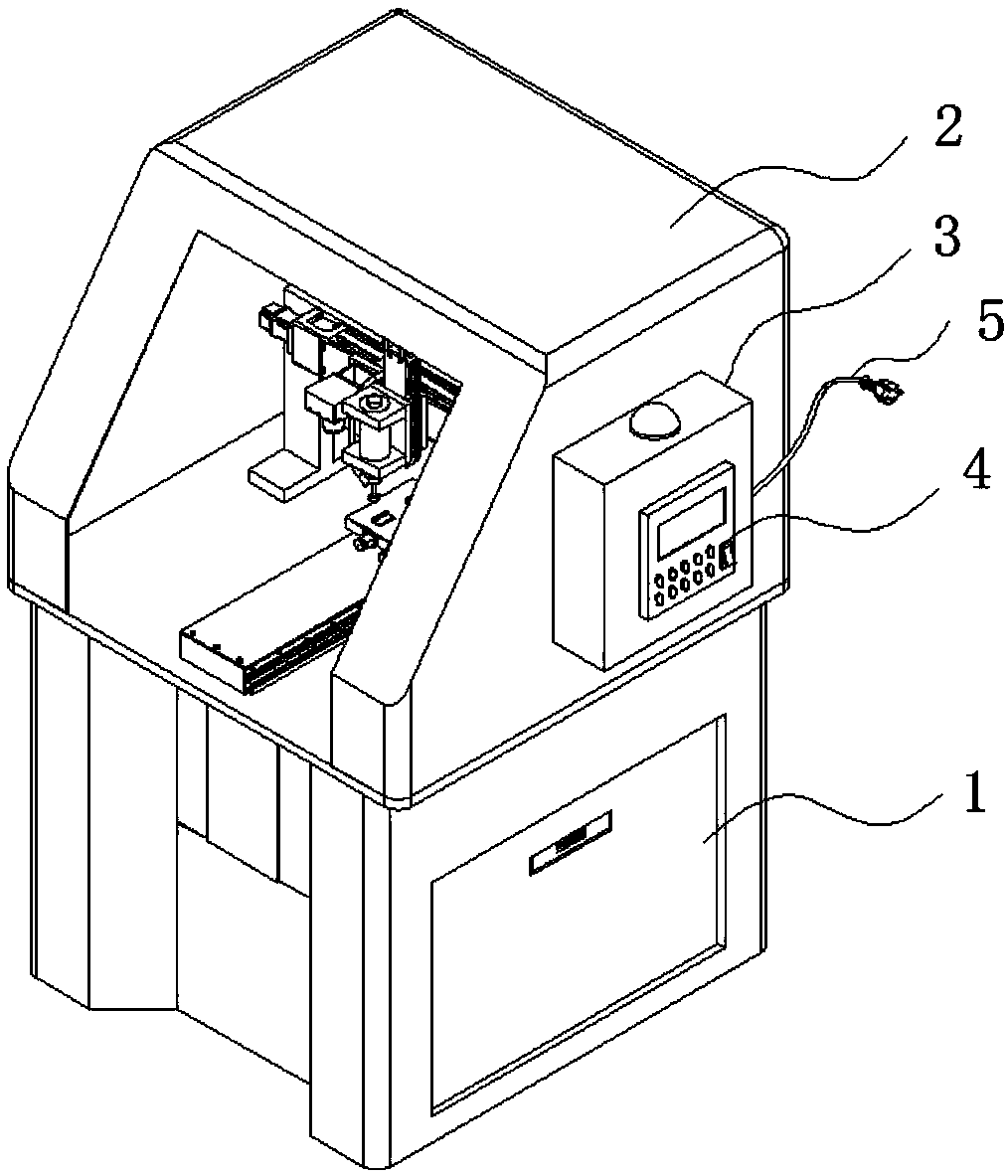
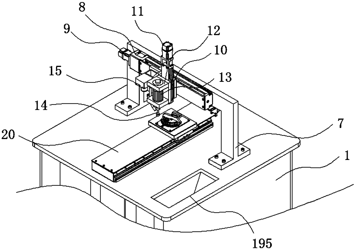
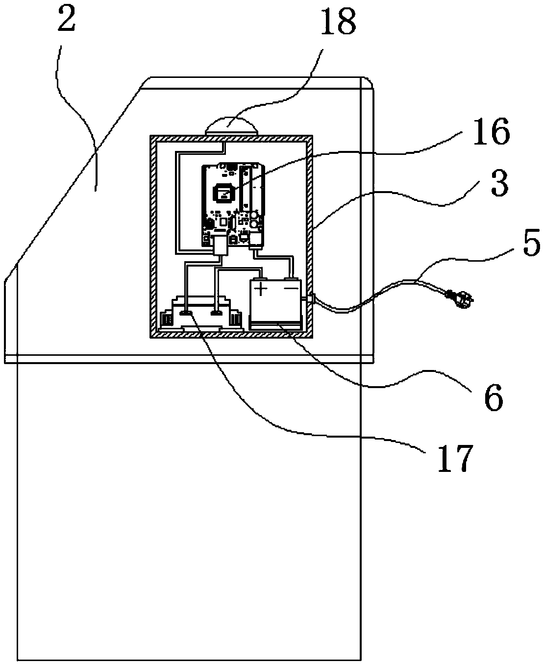
[0048] The following will be combined with Figure 1-9 The present invention is described in detail, and the technical solutions in the embodiments of the present invention are clearly and completely described. Apparently, the described embodiments are only some of the embodiments of the present invention, not all of them. Based on the embodiments of the present invention, all other embodiments obtained by persons of ordinary skill in the art without making creative efforts belong to the protection scope of the present invention.
[0049] The present invention provides an automatic grinding machine for the edge of a workpiece through improvement, including a chassis 1, a chassis cover 2, a distribution box 3, a control panel 4, a power cord 5, a storage battery 6, a frame 7, a lateral sliding mechanism 8, First motor 9, vertical sliding mechanism 10, second motor 11, machine head 12, third motor 13, grinding tool 14, infrared sensor 15, single-chip microcomputer 16, breaker 17...
PUM
Abstract
The invention discloses an automatic grinding machine for workpiece edges. The automatic grinding machine comprises a machine case, a machine case cover, a distribution box, a control panel, a power line, a storage battery, a rack, a transverse sliding mechanism, a first motor, a vertical sliding mechanism, a second motor, a machine head, a third motor, a grinding tool, an infrared sensor, a single chip microcomputer, a circuit breaker, an alarm, a waste chipping collection device, a push mechanism, an angle adjustment mechanism and a clamping device; the machine case cover is welded to the periphery of the outer side of the top of the machine case, a workpiece can be adjusted to be at the appropriate angle after being clamped and fixed, rotation is firstly carried out to release a lockingbolt, then an adjusting plate is rotated to drive the clamping device to conduct left-and-right angle adjustment, the angle of the workpiece can be subjected to left-and-right adjustment, a pointer points to the number of degrees of a scaleplate, the workpiece adjusting angle can be quickly understood, and therefore the problems that after the workpiece is clamped and fixed, the left and right angles cannot be changed, the flexibility is insufficient, and the work efficiency is low are solved, and the flexibility and work efficiency are increased.
Description
technical field [0001] The invention relates to the related field of grinding machines, in particular to an automatic grinding machine for workpiece edges. Background technique [0002] At present, the shapes of wood products are various, especially the workpieces with curved surfaces are difficult to process, and the processing efficiency is relatively low. For the processing of such wood products, grinding machines are mostly used to grind the edges of the workpieces. The subsequent processing of wood products is more convenient and the quality is better. [0003] After searching, it is found that the invention of patent No. CN201420053959.7 discloses a grinding machine for grinding the metal surface of a workpiece, including: at least one grinding assembly; at least one grinding table, the grinding table has at least one a conveyor belt for conveying the workpiece through the grinding machine; and a housing in which the grinding assembly is disposed. [0004] After sear...
Claims
Application Information
Patent Timeline
Application Date:The date an application was filed.
Publication Date:The date a patent or application was officially published.
First Publication Date:The earliest publication date of a patent with the same application number.
Issue Date:Publication date of the patent grant document.
PCT Entry Date:The Entry date of PCT National Phase.
Estimated Expiry Date:The statutory expiry date of a patent right according to the Patent Law, and it is the longest term of protection that the patent right can achieve without the termination of the patent right due to other reasons(Term extension factor has been taken into account ).
Invalid Date:Actual expiry date is based on effective date or publication date of legal transaction data of invalid patent.