
Die for cutting end of semi-elbow pipe sheet metal parts and application method thereof

A technology for sheet metal parts and pipe bends, which is applied in the field of molds for cutting ends of half-bend pipe sheet metal parts. Production quality and production efficiency, and the effect of reducing traffic intensity

Active Publication Date: 2019-02-19
SHENYANG LIMING AERO-ENGINE GROUP CORPORATION
View PDF5 Cites 0 Cited by
  • Summary
  • Abstract
  • Description
  • Claims
  • Application Information

AI Technical Summary

Problems solved by technology

Half of the bent pipe is stretched and formed by sheet metal. After forming, the margin at both ends is removed by milling. Because the part is a thin-walled sheet metal part, the milling cutter cuts intermittently during milling, and the surface finish of the processed surface is poor; in order to To prevent machining deformation, it is laborious to clamp the parts. When milling the two ends, it needs to be processed in two steps separately. The size consistency of the line connecting the center points of the cross-sections of the two ends is poor, and the production efficiency is extremely low.

Method used


Image

  • Die for cutting end of semi-elbow pipe sheet metal parts and application method thereof
  • Die for cutting end of semi-elbow pipe sheet metal parts and application method thereof
  • Die for cutting end of semi-elbow pipe sheet metal parts and application method thereof

Examples


Embodiment Construction

[0019] The present invention will be further described in detail below in conjunction with the accompanying drawings and embodiments.

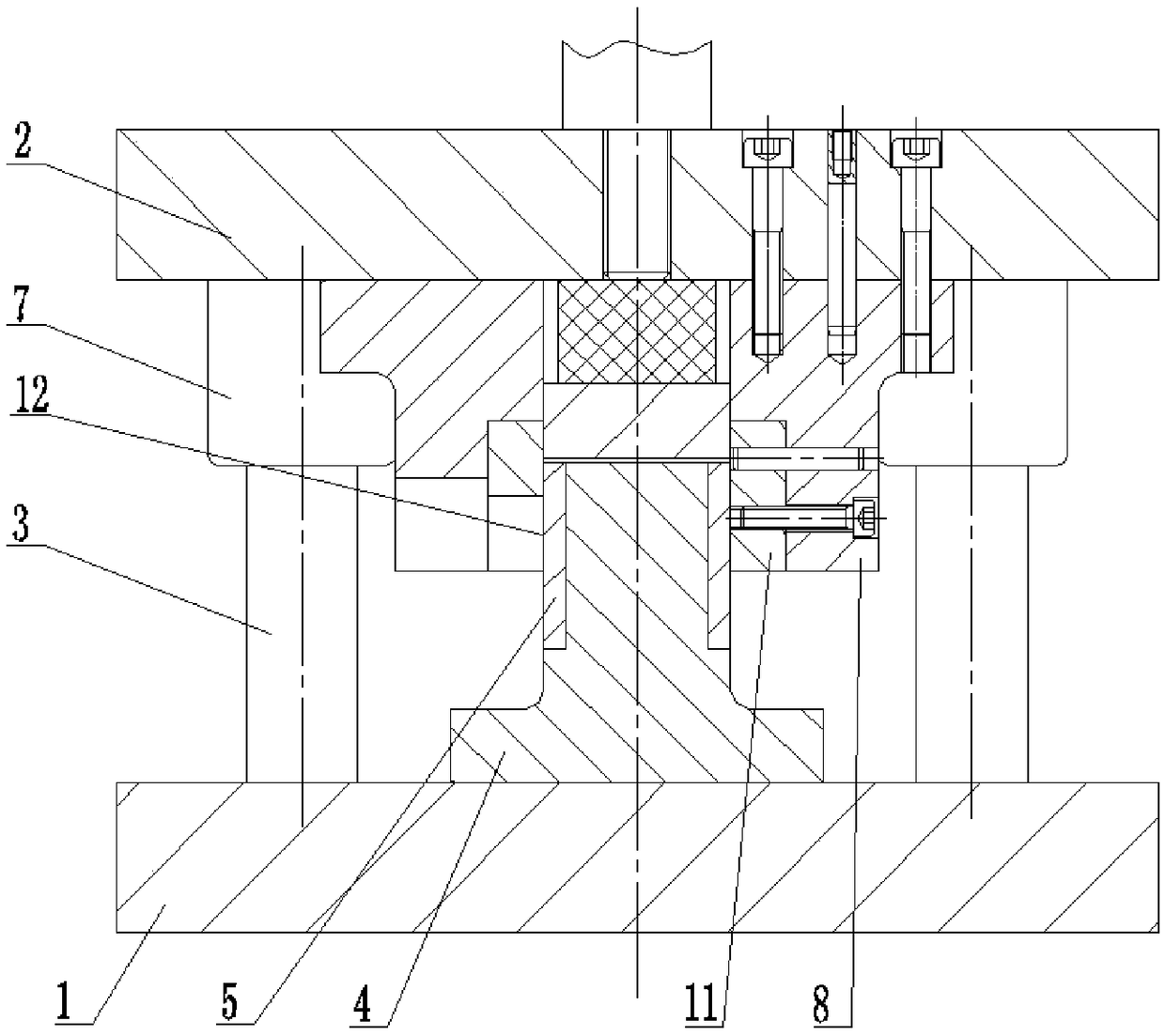
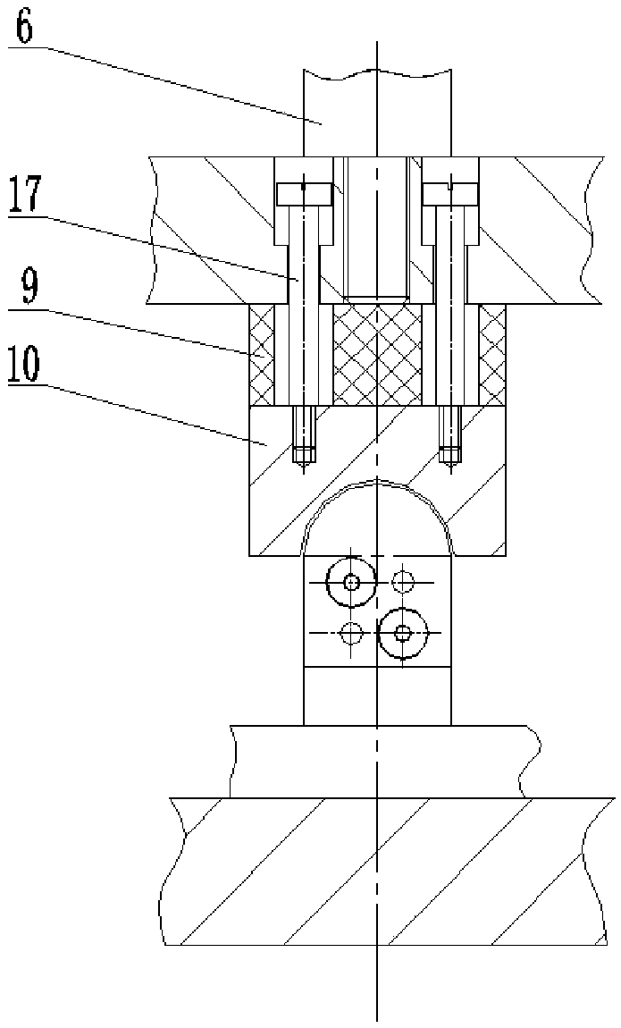
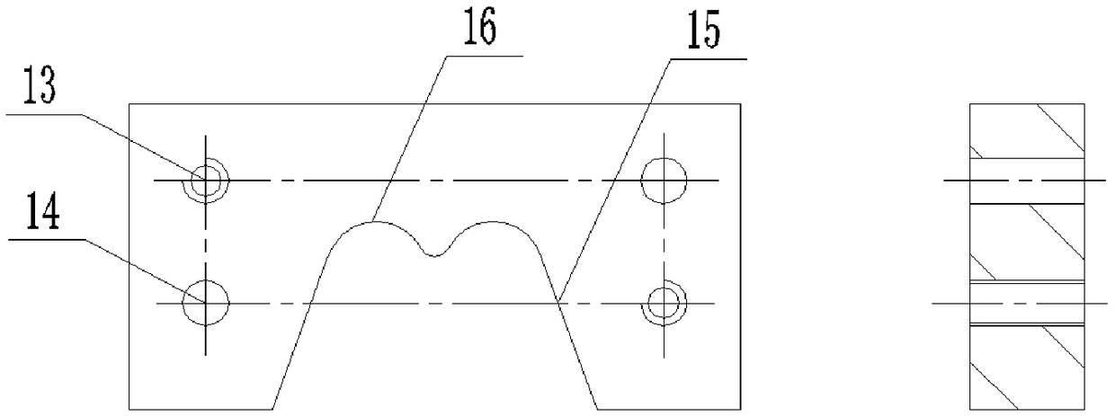
[0020] like Figure 1-Figure 3 As shown in the figure, a mold for cutting end of a half-bending sheet metal part includes a lower template 1 and an upper template 2. The upper surface of the lower template 1 is symmetrically provided with a guide column 3, and the middle of the upper surface of the lower template 1 is provided with a positioning seat 4, so The left and right side walls of the positioning seat 4 are symmetrically provided with positioning pieces 5, and the positioning pieces 5 ensure that the positioning pieces 5 and the cutting blade 11 are worn and replaced by sharpening. The lower surface of the upper template 2 is symmetrically provided with a guide sleeve 7 that cooperates with the guide column 3, the lower surface of the upper template 2 is provided with a blade seat 8 located just above the positioning seat 4, and a step...


PUM


Abstract

The invention discloses a die for cutting end of semi-elbow pipe sheet metal parts and an application method thereof. The die comprise a lower template and an upper template. The upper surface of thelower template is symmetrically provided with guide pillars. The middle of the upper surface of the lower template is provided with a positioning seat. The left and right side walls of the positioningseat are symmetrically provided with positioning plates. The middle of the upper template is connected with a die handle through a thread hole in a threaded mode. The lower surface of the upper template is symmetrically provided with guide sleeves matched with the guide pillars. The lower surface of the upper template is provided with a blade seat positioned over the positioning seat. The middleof the blade seat is provided with a countersunk head hole. Polyurethane rubber is arranged at the bottom of the upper template. The polyurethane rubber is located in a small hole of the countersunk head hole. The lower surface of the polyurethane rubber is provided with a pressing block. The inner wall of a large hole of the countersunk head hole of the blade seat is provided with a cutting blade. The inner surface of the cutting blade is flush with the surface of the small hole. By setting a cutting edge in the die, the blade performs end cutting and blanking bidirectionally in the cutting process, so that two-step separated processing is avoided, and the processing quality of end faces and the consistency of the connecting line size of cross section centers of the two end faces are improved.

Description

technical field [0001] The invention belongs to the technical field of mechanical processing, and particularly relates to a mold for cutting ends of a half-bending sheet metal part and a method for using the same. Background technique [0002] The half-bend is a "U"-shaped annular metal thin-walled part of the busbar. The vertical busbar has a semicircular structure. The "U"-shaped busbar includes an angle of 30 degrees. The half elbow is formed by sheet metal drawing. After forming, the allowance at both ends is removed by milling. Because the part is a thin-walled sheet metal part, the milling cutter is interrupted during milling, and the surface finish of the machined surface is poor; in order to To prevent machining deformation, it is more laborious to clamp parts. When milling both ends, it needs to be processed separately in two steps. The size of the connection between the center points of the cross-sections at both ends is poor, and the production efficiency is extre...

Claims


Application Information

Patent Timeline
IPC IPC(8): B21D28/02B21D28/04B21D28/14
CPCB21D28/02B21D28/04B21D28/14
Inventor 吴蓉昆段新民何移峰赵兰州刘翾
Owner SHENYANG LIMING AERO-ENGINE GROUP CORPORATION
Learn More