A spring coil electromagnetic release device

A release device and spring coil technology, which is applied in the field of medical devices, can solve the problems of reducing the controllability of the spring coil, making it difficult to pull back or advance, and affecting the operation time, so as to ensure the controllability and improve the accuracy of the placement position. Effect

Active Publication Date: 2020-10-16
NANHUA UNIV
View PDF6 Cites 0 Cited by
  • Summary
  • Abstract
  • Description
  • Claims
  • Application Information

AI Technical Summary

Problems solved by technology

Due to its poor controllability, hydrolytic release coils are rarely used clinically; most of the electrolytic release coils used in clinical practice have the problem that the release time is too long or unstable, which affects the operation time
Moreover, the electrolytic release main contact is mainly formed by welding, which requires chemical fusing of the main contact, so there is a risk of blood vessel damage; the simple snap-in design of the mechanical release spring coil can achieve instantaneous release of the spring coil, but it reduces the packing process The controllability of the spring coil, especially when the coil is pushed out of the channel, it is difficult to pull back or push
Patent Document 1 (publication number CN107951525A) discloses a mechanical release device, which uses a core wire to lock the first protrusion of the spring coil and the second protrusion of the push rod in the axial direction, and uses the inside of the push rod to move The core wire is used to lock or unlock the connection between the push rod and the spring coil to release the spring coil, but the manufacturing cost of the core wire is high, and the assembly requirements are high, and after the spring coil is released, the second protrusion is extremely difficult when the push rod withdraws. It may interfere with the first protruding part, thereby changing the placement position of the disengaged spring coil, affecting the accuracy of the placement position, and limiting the application of this mechanical release device

Method used


Image

  • A spring coil electromagnetic release device
  • A spring coil electromagnetic release device
  • A spring coil electromagnetic release device

Examples


Embodiment Construction

[0020] The present invention will be described in further detail below in conjunction with the accompanying drawings.

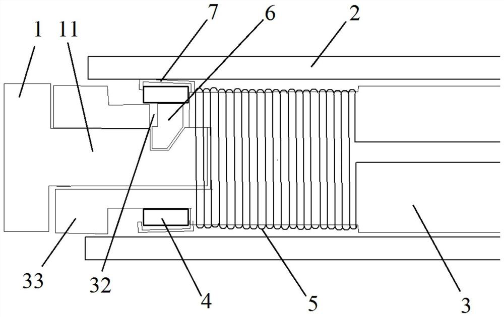
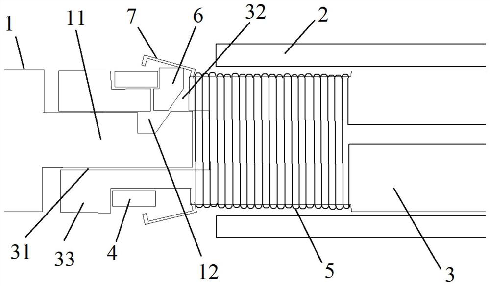
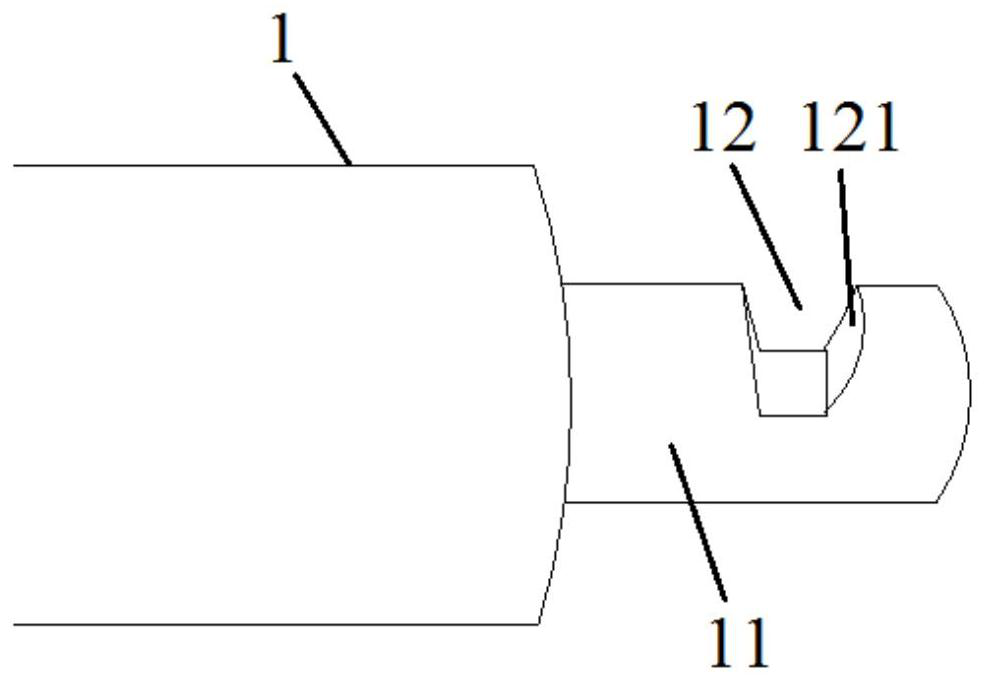
[0021] see Figure 1-4 , a spring coil electromagnetic release device, which includes a spring coil 1, a guide tube 2 and a push rod 3 set inside the guide tube 2, the end of the coil coil 1 has a rod-shaped joint 11, and a card slot is opened on the joint 11 12. The end of the push rod 3 is provided with an accommodating hole 31 for accommodating the joint 11, and the accommodating hole 31 extends along the axial direction of the push rod 3; the end of the push rod 3 is also sleeved with a ring magnet 4 Compared with the coil 5, the ring magnet 4 is closer to the spring coil 1 than the coil 5. A flange can be arranged between the ring magnet 4 and the coil 5 to prevent the ring magnet 4 from contacting the coil 5. The coil 5 is fixedly connected to the push rod 3, and the ring The magnet 4 is movably connected with the push rod 3 and can move along the axia...


PUM


Abstract

The invention discloses an electromagnetic releasing device for a spring ring. The device comprises the spring ring, a guide pipe, a magnetic positioning bolt and a push rod arranged in the guide pipe, the end of the spring ring is provided with a joint part, and the joint part is provided with a clamping groove; the end of the push rod is provided with a containing hole used for containing the joint part; the end of the push rod is further sleeved with an annular magnet and a coil, the annular magnet is movably connected with the push rod, and the push rod is provided with a positioning holerunning through the containing hole and the outer surface of the push rod; the positioning bolt can be contained in the positioning hole and the clamping groove simultaneously; the annular magnet limits the positioning bolt in the positioning hole and the clamping groove when being located on a locking position; when the annular magnet moves from the locking position to an unlocking position underpushing of the coil, the positioning bolt can exit from the clamping groove. The electromagnetic releasing device for the spring ring has the advantages that the spring ring can be reliably jointed with the push rod before being released; when the spring ring needs to be released, the annular magnet is pushed to the unlocking position by using the magnetic force to achieve instant releasing of the spring ring, thereby improving the accuracy of the placement position of the spring ring.

Description

technical field [0001] The invention relates to the field of medical devices, in particular to an electromagnetic release device for spring coils. Background technique [0002] Since the 1980s, clinical interventional techniques have been used to embolize aneurysms. In the early days, detachable balloons were used as embolization embolisms. The aneurysm cannot be fully embolized. The coil can fully fill and adapt to the shape of the aneurysm lumen, so the embolization of aneurysms with coils has become the main treatment for aneurysms. [0003] In the interventional operation of coil embolization of aneurysms, it is necessary to deliver coils of different sizes and different three-dimensional or two-dimensional shapes into the aneurysm from large to small until the springs in the aneurysm can densely pack the entire aneurysm. Clinically, interventional surgery for each aneurysm usually requires several to a dozen coils to complete the dense packing of the aneurysm. On the...

Claims


Application Information

Patent Timeline
Patent Type & Authority Patents(China)
IPC IPC(8): A61B17/12
CPCA61B17/12113A61B17/1214A61B2017/12086
Inventor 尹凯张耀元曾琳赵亚忠
Owner NANHUA UNIV
Why Eureka
Try Eureka