Novel vacuum tube

A vacuum tube, a new type of technology, applied in the field of vacuum tubes, can solve the problem of large torque of bellows, and achieve the effect of preventing easy breakdown by high voltage electricity

Inactive Publication Date: 2019-02-15
NANTONG ZISHENG TECH CO LTD
View PDF0 Cites 0 Cited by
  • Summary
  • Abstract
  • Description
  • Claims
  • Application Information

AI Technical Summary

Problems solved by technology

[0004] The purpose of the present invention is to solve the problem of excessive bellows torque in the prior art, and propose a new type of vacuum tube

Method used


Image

  • Novel vacuum tube
  • Novel vacuum tube

Examples


Embodiment Construction

[0018] The following will clearly and completely describe the technical solutions in the embodiments of the present invention with reference to the accompanying drawings in the embodiments of the present invention. Obviously, the described embodiments are only some, not all, embodiments of the present invention.

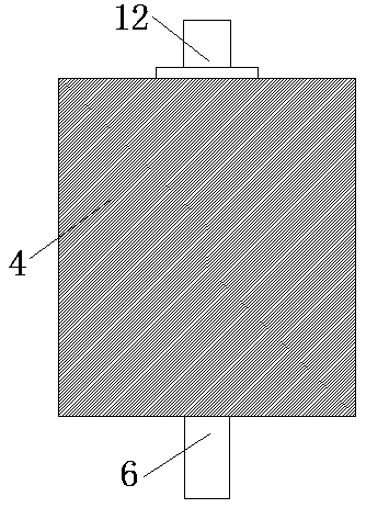
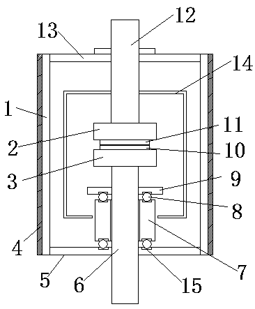
[0019] refer to Figure 1-2 , a new type of vacuum tube, including a porcelain cylinder 1, a movable end cover 5 is fixedly connected to the inner side wall of the bottom of the porcelain cylinder 1, a movable conductive rod 6 is slidably connected to the movable end cover 5, and the top of the movable end cover 5 is provided with The sliding opening corresponding to the movable conductive rod 6, the outer wall of the movable conductive rod 6 is fixedly connected with a support mechanism, the support mechanism includes a limit ring 9 fixedly sleeved on the outer wall of the movable conductive rod 6, and the outer wall of the movable conductive rod 6 rotates A corruga...


PUM


Abstract

The invention discloses a novel vacuum tube. The novel vacuum tube comprises a porcelain cylinder, wherein a movable end cover plate is fixedly connected with an inner-side wall of the bottom of the porcelain cylinder, a movable conductive rod is connected to the movable end cover plate in a sliding way, a sliding opening is formed in the top of the movable end cover plate and is corresponding tothe movable conductive rod, and a support mechanism is fixedly connected with an outer-side wall of the conductive rod. In the novel vacuum tube, the top of a corrugated tube is connected with a limitation ring by a plurality of balls under a matching effect of the first balls, the limitation ring, second balls, the corrugated tube, the movable conductive rod and the movable end cover plate, the bottom of the corrugated tube is connected with the movable end cover plate by a plurality of second balls, the corrugated tube is driven to simultaneously rotate by the movable conductive rod, and thefunction of preventing the movable conductive rod from rotating to cause excessively large torque of the corrugated tube is achieved; and by a matching effect of the porcelain cylinder and a siliconrubber layer, the effect that the silicon rubber layer wraps an outer surface of the porcelain cylinder is achieved, and the function that an external insulation layer of a vacuum arc tube is easily broken down by a high voltage.

Description

technical field [0001] The invention relates to the technical field of vacuum tubes, in particular to a novel vacuum tube. Background technique [0002] Vacuum tubes, also known as vacuum switching tubes, are the core components of medium and high voltage power switches. The excellent insulation of the vacuum inside the tube enables the medium and high voltage circuits to quickly extinguish the arc and suppress the current after the power supply is cut off, so as to avoid accidents and accidents. [0003] The current vacuum tube will be installed on the positive electrode during use, and the torque of the bellows will be too large due to the twisting of the conductive rod, resulting in reduced service life of the vacuum tube or air leakage failure. Contents of the invention [0004] The purpose of the present invention is to solve the problem of excessive torque of the bellows in the prior art, and propose a new type of vacuum tube. [0005] In order to achieve the above...

Claims


Application Information

Patent Timeline
IPC IPC(8): H01H33/66H01H33/662H01H33/664
CPCH01H33/66H01H33/66238H01H33/664
Inventor 陈忠邱向欣梁义颜金战徐春梅
Owner NANTONG ZISHENG TECH CO LTD
Why Eureka
Try Eureka