Pipeline smoke heating device

A flue gas heating and heating device technology, which is applied in the field of flue gas heating, can solve problems such as separate configuration, and achieve the effects of reasonable flame length, flame protection, and pipe wall protection

Active Publication Date: 2019-02-15
WUHAN UNIV OF TECH +1
View PDF9 Cites 0 Cited by
  • Summary
  • Abstract
  • Description
  • Claims
  • Application Information

AI Technical Summary

Problems solved by technology

[0007] In view of this, the purpose of the present invention is to provide a pipe flue gas heating device, which can solve the defects of the external hot blast stove flue gas heating method that need to be equipped with high-temperature flue and fan separately, and can save the flue gas temperature while ensuring the flue gas temperature cost

Method used


Image

  • Pipeline smoke heating device
  • Pipeline smoke heating device
  • Pipeline smoke heating device

Examples


Embodiment 1

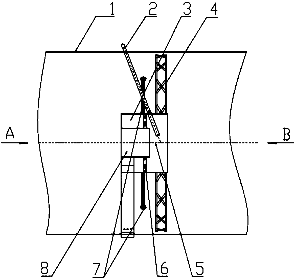
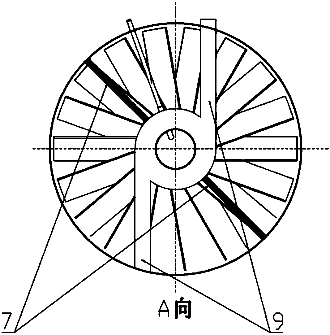
[0030] Such as Figure 1-3 As shown, the present invention provides a pipeline flue gas heating device. The heating device is fixed in the flue 1 and includes a secondary flue gas channel 10 coaxially arranged in sequence from outside to inside, a gas swirl chamber 3 and a central wind 8, the channel wall of the secondary flue gas channel 10 is fixedly connected with the flue wall of the flue 1, and an inclined gas swirl vane 6 is arranged between the outer wall of the outlet of the central air duct 8 and the inner wall of the gas swirl chamber 3 , the gas swirl blade 6 and the central air duct 8 front end form a combustion chamber 5, and the rear end forms a gas swirl chamber 3, the gas pipeline 9 communicates with the gas swirl chamber 3 to feed gas, and the ignition gun 2 passes through each outer layer The wall surface is inserted into the combustion chamber 5, and several layers of inclined smoke swirl vanes 4 are arranged between the outer wall of the coal gas swirl cham...

Embodiment 2

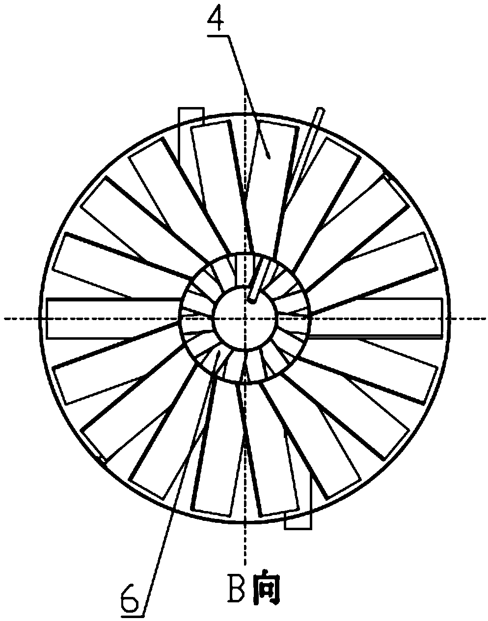
[0037] Such as Figure 4-5As shown, the difference between the second embodiment and the first embodiment is that there are multiple layers of secondary flue gas passages 10 in the second embodiment, and flue gas swirl vanes 4 are arranged between each layer of secondary flue gas passages 10 . The number of layers of the secondary flue gas channel 10 can be designed according to the diameter of the flue.

[0038] Working principle of the present invention: In the present invention, the gas is input into the gas swirl cavity 3 through the gas pipeline 9, and the gas forms a whirlwind in the gas swirl cavity 3, and the flue gas in the gas swirl blade 6 and the central air duct 8 Premixing is carried out, the premixed gas flows into the combustion chamber 5, and is ignited by the ignition gun 2 in the combustion chamber 5; at the exit of the secondary flue gas channel 10, the flue gas swirl blade 4 with the opposite direction is arranged. If there are multiple layers of secondary...


PUM


Abstract

The invention discloses a pipeline smoke heating device. The heating device is fixedly into a flue, and comprises a secondary smoke channel, a gas rotational flow cavity and a center air channel fromoutside to inside. Inclined gas rotational flow blades are arranged between the outer wall of the outlet of the center air channel and the inner wall of the gas rotational flow cavity. A combustion cavity is formed in the front ends of the gas rotational flow blades and the center air channel, and a gas rotational flow cavity is formed in the rear ends of the gas rotational flow blades and the center air channel. The gas pipeline communicates with the gas rotational flow cavity, and is filled with the gas. A burning torch penetrates through outer layer walls and is inserted into the combustioncavity. A plurality layers of inclined smoke rotational blades are arranged between the outer wall of the gas rotational flow cavity and the inner wall of the secondary smoke channel. Oxygen in the smoke is adopted to complete combustion and release heat to increase the temperature of the smoke. The shape and size of flame are controlled by the rotational flow blades, and therefore the length ofthe flame is reasonable and the radius of the flame is less than the diameter of a chimney. Damage caused by superheat of the flue is avoided. The temperature rising process of the smoke is completedby the heat exchanging between cold smoke and hot smoke. The process is direct, the cost is saved, energy is saved, and efficiency is achieved.

Description

technical field [0001] The invention relates to the technical field of flue gas heating, in particular to a pipeline flue gas heating device. Background technique [0002] With the acceleration of industrialization and urbanization and the continuous upgrading of consumption structure, my country's demand for energy continues to grow, and resource and environmental protection issues are still one of the bottlenecks restricting my country's economic development. Nitrogen oxide pollution is another important environmental problem after sulfur dioxide pollution. In order to make the emission concentration of air pollutants basically meet the emission limit requirements of gas-fired units, the state requires that the maximum allowable emission concentration of nitrogen oxides should not be higher than 50mg / Nm 3 , where nitrogen oxides generally refer to NO, NO 2 , NO 3 , N 2 O, N 2 o 3 etc., collectively referred to as NO X . NO from boiler combustion X Seriously pollut...

Claims


Application Information

Patent Timeline
Patent Type & Authority Applications(China)
IPC IPC(8): F23C9/06F23J15/08
CPCF23C9/06F23J15/08
Inventor 陈作炳欧冶金毛娅曹菁于永杰程松
Owner WUHAN UNIV OF TECH
Why Eureka
Try Eureka