Trolley bus braking system and trolley bus
A technology of trolleybus and braking system, which is applied in the direction of railway braking system, pneumatic brake, railway car body parts, etc., and can solve problems such as inapplicability
- Summary
- Abstract
- Description
- Claims
- Application Information
AI Technical Summary
Problems solved by technology
Method used
Image
Examples
Embodiment 1
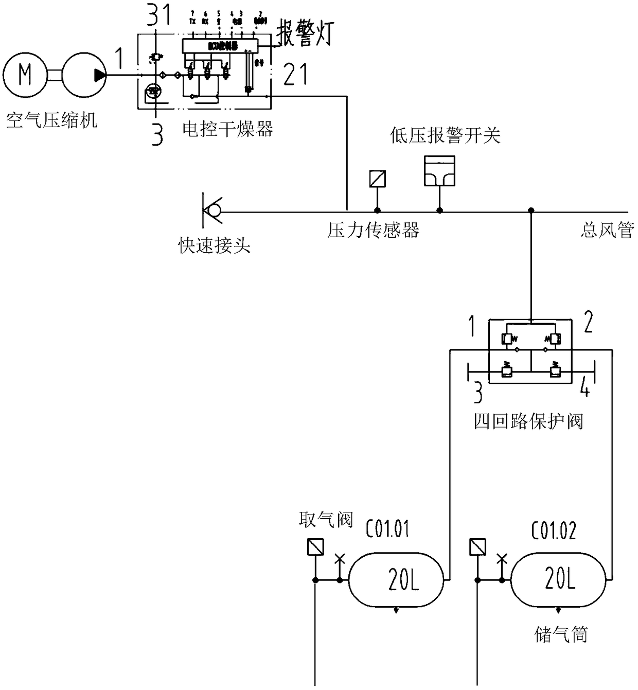
[0076] A trolley bus, including a car body and a vehicle electronic control unit (vehicle ECU), which is provided with 6 axles, which are numbered from the front to the rear as the No. 1 axle to the No. 6 axle. The trolley bus can run in both directions. Both ends of the trolley bus are provided with a driving area and an instrument panel, the instrument panel is provided with an emergency brake switch, and the driving area is provided with an electric brake main valve and a parking brake control valve. The braking system of the trolley bus includes an air source subsystem and a ventilation pipeline subsystem, and also includes a brake control subsystem and an electrical system, and the wind source subsystem and the brake control subsystem pass through the ventilation pipeline sub-system system connection, the electrical system and the braking control subsystem are connected through a circuit.
[0077] The wind source subsystem meets the requirements of GB 7258-2012, that is, ...
Embodiment 2
[0081] The trolley bus braking system also includes an electronically controlled air suspension subsystem (ECAS), and the ECAS is connected to the wind source subsystem through pipelines and connected to the electrical system through circuits.
[0082] The electronically controlled air suspension subsystem includes an ECAS solenoid valve, an inductive height valve, a two-way one-way valve, an air intake valve, a pressure sensor and an air bag. ECAS solenoid valves are arranged on the No. 2 wheel shaft and the No. 5 wheel shaft, wherein the ECAS solenoid valve on the No. 2 wheel shaft is connected with the two-way one-way valve set on the No. The pressure sensor and the air bag on the No. 2 wheel shaft are connected through a pipeline to connect the pressure sensor and the air bag on the No. 2 wheel shaft, and the pressure sensor and the air bag on the No. 3 wheel shaft are connected through a line of pipelines; The ECAS solenoid valve is connected to the two-way one-way valve ...
Embodiment 3
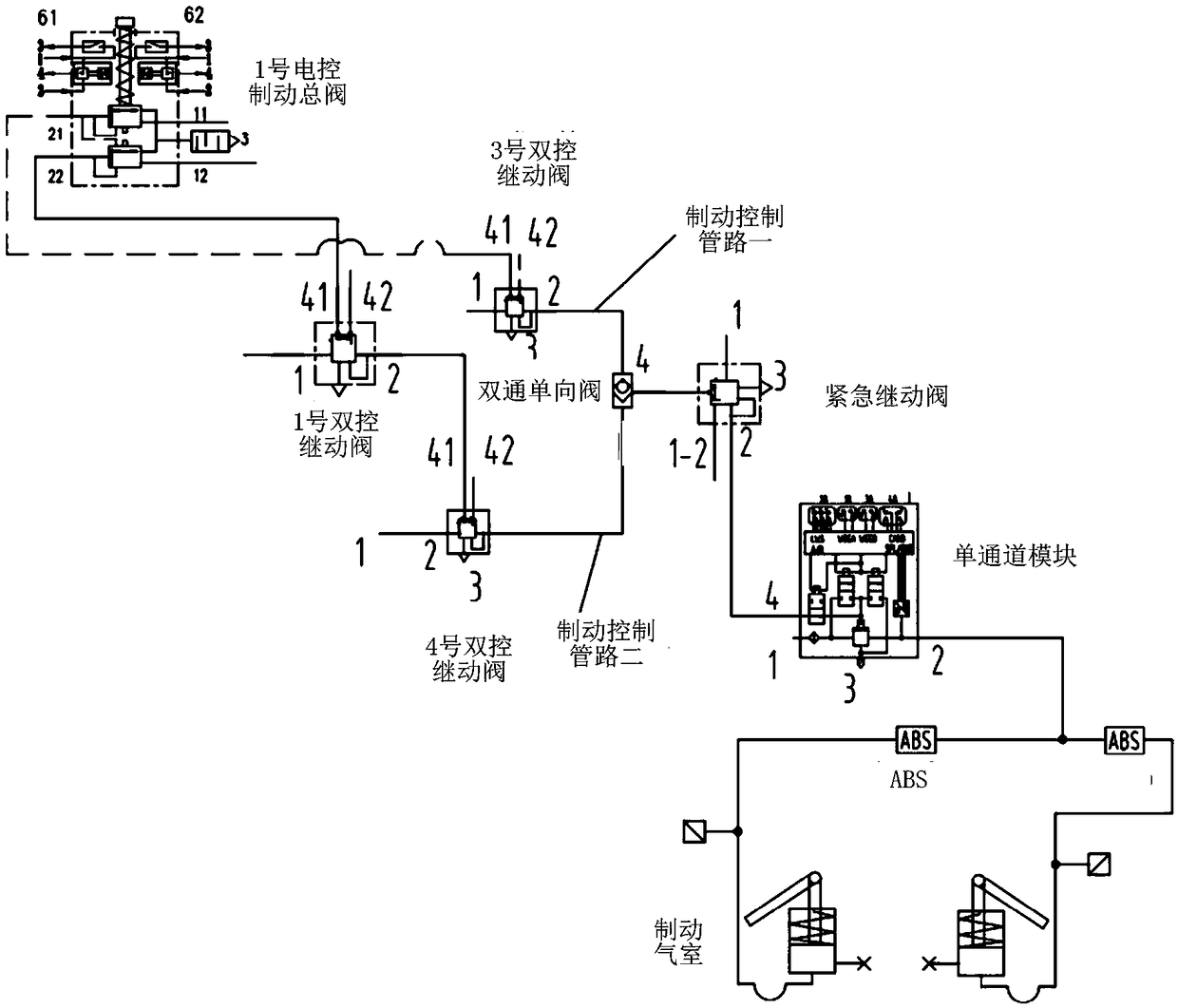
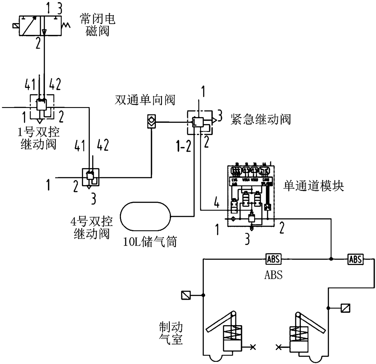
[0085] The brake control subsystem includes an electric brake master valve, a dual-control relay valve, a two-way one-way valve, an emergency relay valve, a single-channel module, ABS and a brake.
[0086] The electric brake master valve has two independent air brake circuits, and the air outlet of each air brake circuit leads to a brake control pipeline, that is, the electric brake master valve leads to two independent air brake circuits. Brake control line. There are two electronically controlled brake master valves, which are respectively set in the driving areas at both ends of the trolley bus, and one of the electronically controlled brake master valves (No. The gas storage tank C01.01, C01.02 of the air outlet is connected, and another electronically controlled brake master valve (No. 2 electric control brake master valve) is connected to the air storage tank C06.01, C06. 02 Air outlet connection. There are dual-control relay valves on the No. 1 axle, No. 3 axle, No. 4...
PUM
 Abstract
Description
Claims
Application Information
 - R&D
- Intellectual Property
- Life Sciences
- Materials
- Tech Scout
- Unparalleled Data Quality
- Higher Quality Content
- 60% Fewer Hallucinations
Browse by: Latest US Patents, China's latest patents, Technical Efficacy Thesaurus, Application Domain, Technology Topic, Popular Technical Reports.
© 2025 PatSnap. All rights reserved.Legal|Privacy policy|Modern Slavery Act Transparency Statement|Sitemap|About US| Contact US: help@patsnap.com


