


Quick Research
Generate reliable direction feasibility study reports for your R&D in just a few steps.

Technical Q&A
Discover and master advanced knowledge NOW. Basics, ideas, possibilities, all at once.

Find Solutions
As an expert in R&D theories, this can generate solutions to your technical problems instantly.

Evaluate Feasibility
Analyze your overall solution with one click, know your potential R&D risks in advance.

Monitor Landscape
Get weekly tech updates, stay abreast of the latest tech innovations and key insights.
Nozzle needle tip calibration method and low temperature printing platform based on 3D printer
A technology of 3D printer and calibration method, applied in the field of 3D printing, can solve the problems of no material extrusion of the needle tip, time-consuming calibration process, affecting printing efficiency, etc., to achieve the effect of rapid dismantling, shortening calibration time, and improving efficiency
- Summary
- Abstract
- Description
- Claims
- Application Information
AI Technical Summary
Problems solved by technology
Method used
Image


Examples
Embodiment 1
[0049] like Figure 1-5 , use the A sensor to calibrate the position of the needle tip of the nozzle with the conventional one-touch type and the two-touch type of the present application respectively, and set the actual initial distance between the needle tip and the calibration plane of the position sensor at the initial calibration as χ, the technology of the A sensor The parameters are shown in Table 1:
[0050] Rated stroke
5mm
1um
effective operating speed
Operating speed 50~200mm / min
Contact life
3 million times
protective structure
IP67
1.5N
Contact material
[0051] Table 1
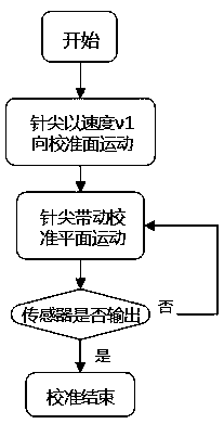
[0052] The process of using the conventional one touch to calibrate the nozzle tip position is as follows: figure 2 As shown, the calibration principle is as image 3 As shown, the needle tip touches the calibration plane of the position sensor 1 at the speed V1 and ...
Embodiment 2
[0060] Use the B sensor to calibrate the position of the needle tip of the nozzle with the conventional one-touch type and the two-touch type of the application, and set the actual initial distance between the needle tip and the calibration plane of the position sensor at the initial calibration as χ, the technical parameters of the B sensor As shown in table 2:
[0061]
[0062]
[0063] Table 2
[0064] The verification principle adopted in this embodiment is the same as that in Embodiment 1. We can know that the limit speed of V2 is 70.7mm / s by substituting it into the calculation. It is also stipulated that the range of V3≥V2 and V2=V3=70mm / s is substituted into the calculation, and x can be obtained M =5.995mm, that is, when the actual initial distance χ>5.995mm, the two-touch calibration can effectively shorten the needle tip calibration time and improve the calibration efficiency without affecting the calibration accuracy compared with the conventional one-touch c...
Embodiment 3
[0066] Use the C sensor to calibrate the position of the needle tip of the nozzle with the conventional one-touch type and the two-touch type of the application, and set the actual initial distance between the needle tip and the calibration plane of the position sensor at the initial calibration as χ, the technical parameters of the C sensor as shown in Table 3:
[0067] Rated stroke
5mm
0.5um
effective operating speed
50~200mm / min
Contact life
3 million times
protective structure
IP67
3N
Contact material
[0068] table 3
[0069] The verification principle adopted in this embodiment is the same as that of Embodiments 1 and 2. We can know that the limit speed of V2 is 77.5mm / s by substituting it into the calculation. It is also stipulated that the range of V3≥V2 and take V2=V3=77mm / s into the calculation, which can be obtained x M =5.910mm, that is,...
PUM
 Abstract
Description
Claims
Application Information
 - R&D Engineer
- R&D Manager
- IP Professional
- Industry Leading Data Capabilities
- Powerful AI technology
- Patent DNA Extraction
Browse by: Latest US Patents, China's latest patents, Technical Efficacy Thesaurus, Application Domain, Technology Topic, Popular Technical Reports.
© 2024 PatSnap. All rights reserved.Legal|Privacy policy|Modern Slavery Act Transparency Statement|Sitemap|About US| Contact US: help@patsnap.com