
Square crystal bar grinding and chamfering integrated machine

An all-in-one machine and ingot technology, which is applied in the direction of grinding racks, grinding machine parts, machine tools suitable for grinding workpiece planes, etc., can solve the problems of complex processing technology, high processing cost, and low processing efficiency. Achieve the effect of improving processing efficiency, reducing processing cost and reducing waste

Pending Publication Date: 2019-02-15
LESHAN TOPRAYCELL
View PDF11 Cites 1 Cited by
  • Summary
  • Abstract
  • Description
  • Claims
  • Application Information

AI Technical Summary

Problems solved by technology

The whole processing process requires three kinds of processing equipment with different functions. Silicon rods need to be frequently manually moved between different devices, and the clamping and operation before processing are generally completed by workers, which brings positioning errors.
[0003] When grinding polycrystalline silicon rods, the existing grinding device generally grinds the surface of the crystal rod by clamping one end of the polycrystalline silicon rod. Since the clamping end cannot achieve surface grinding, after grinding one end of the crystal rod, it is necessary to Clamp the other end to grind the unground end, which makes the processing process complicated and the processing efficiency low
[0004] After the polycrystalline silicon rods are ground, since the polycrystalline silicon wafers need to be chamfered, in order to reduce the chamfering of each silicon wafer, it is necessary to chamfer the square silicon rods. The existing silicon rod chamfering is generally It is to chamfer the two corners of the upper end of the silicon rod, turn over the silicon rod and then chamfer the remaining two corners, which makes the processing process complicated, the processing efficiency low, and the processing cost high

Method used


Image

  • Square crystal bar grinding and chamfering integrated machine
  • Square crystal bar grinding and chamfering integrated machine
  • Square crystal bar grinding and chamfering integrated machine

Examples


Embodiment Construction

[0041] The present invention will be further described below in conjunction with the accompanying drawings and embodiments.

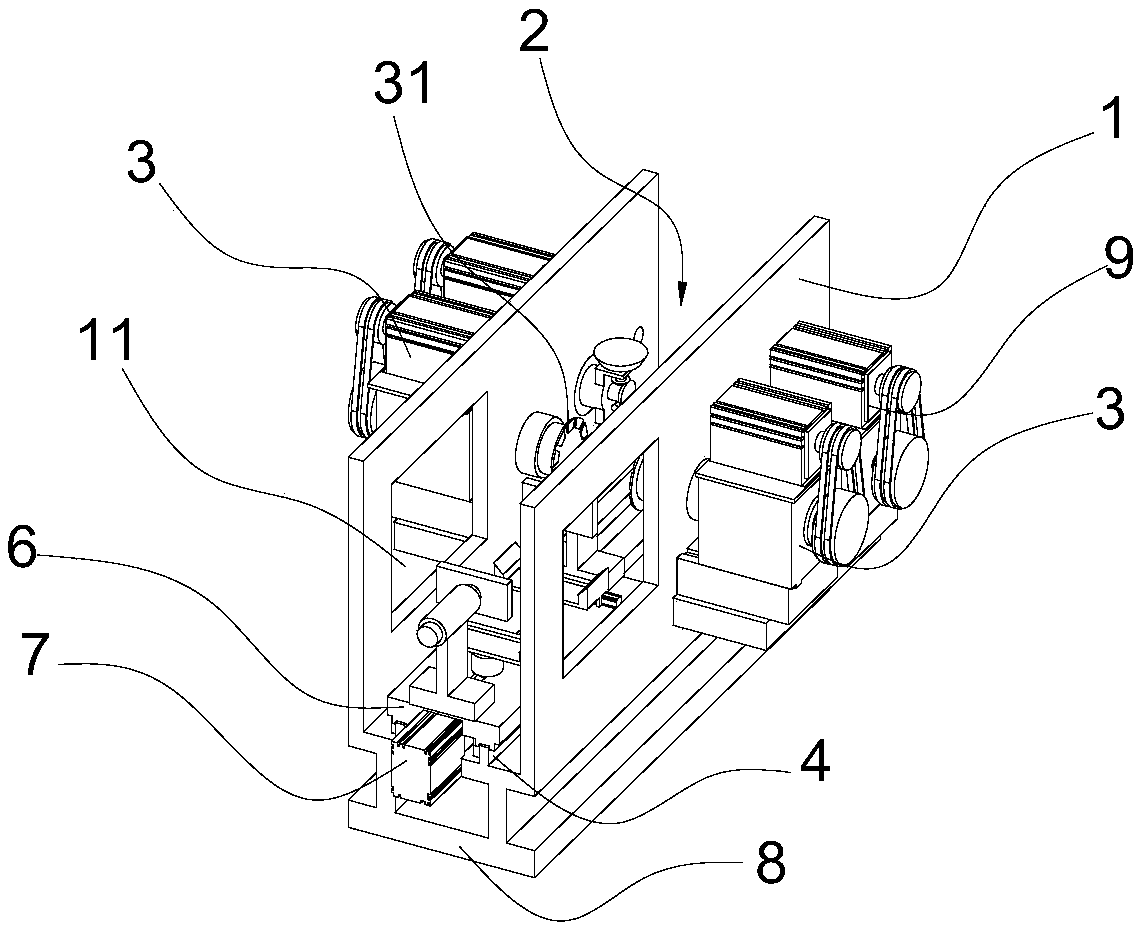
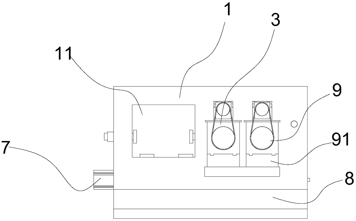
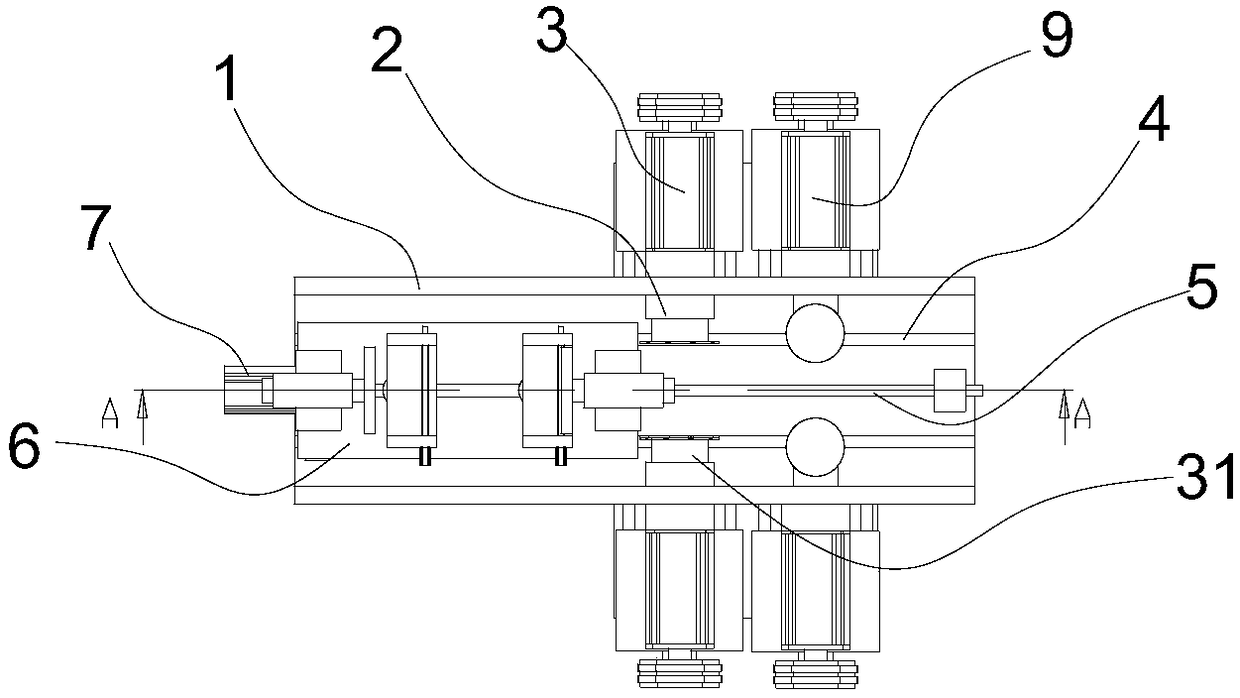
[0042] Such as Figure 1 to Figure 10 As shown, the all-in-one machine for grinding square crystal ingots according to the present invention includes a body 1, and a horizontal working cavity 2 is arranged in the body 1;

[0043] The bottom of the transverse working cavity 2 is provided with an ingot clamping device, and one end of the body 1 is provided with a discharge window 11; both sides of the other end of the body 1 are provided with a grinding device 3 and a chamfering device 9; the grinding device 3 is located between the discharge window 11 and the chamfering device 9;

[0044] The grinding device 3 has a grinding head 31, and the grinding head 31 extends into the transverse working cavity 2; the chamfering grinding wheel 910 of the chamfering device 9 extends into the transverse working cavity 2;

[0045] Described chamfering device 9 compr...


PUM


Abstract

The invention discloses a square crystal bar grinding and chamfering integrated machine capable of simultaneously finishing chamfering of four corners of a crystal bar at a time, grinding the two opposite side faces of the crystal bar at the same time, improving the work efficiency and reducing the cost. The square crystal bar grinding and chamfering integrated machine comprises a machine body internally provided with a transverse work through cavity; a crystal bar clamping device is arranged at the bottom of the transverse work through cavity, and a discharging window is arranged at one end of the machine body; and grinding devices and chamfering devices are arranged on the two sides of the other end of the machine body; the grinding devices are located between the discharging window andthe chamfering devices; the grinding devices are provided with grinding heads, and the grinding heads extend into the transverse work through cavity; and the chamfering devices are provided with chamfering grinding wheels extending into the transverse work through cavity. By adoption of the square crystal bar grinding and chamfering integrated machine, the crystal bar face grinding and chamferingefficiency can be improved, meanwhile, positioning errors can be reduced, and silicon material waste can be reduced.

Description

technical field [0001] The crystal ingot processing involved in the present invention is, in particular, an integrated machine for grinding and pouring square crystal ingots. Background technique [0002] It is well known that the silicon rods of polycrystalline silicon are generally rectangular silicon rods, and the silicon rods of monocrystalline silicon are cylindrical. At present, the traditional processing method for the cutting, grinding and filleting of monocrystalline silicon rods at home and abroad is a separate Landau process, that is, three different equipment are used to complete the entire process of monocrystalline silicon rods. Processing process. In actual operation, the wire squaring machine usually needs to use glue to square 25 single crystal silicon rods at the same time. Surface grinding machine for surface grinding and polishing. The whole processing process requires three kinds of processing equipment with different functions. Silicon rods need to b...

Claims


Application Information

Patent Timeline
IPC IPC(8): B24B27/00B24B7/22B24B9/06B24B41/06B24B41/02B24B47/12
CPCB24B7/22B24B9/06B24B27/0023B24B27/0069B24B41/02B24B41/06B24B47/12
Inventor 陈五奎陈嘉豪任超曹卫宏陈辉
Owner LESHAN TOPRAYCELL
Learn More