Automatic beveling machine

A chamfering machine, automatic technology, applied in the field of component processing, can solve the problems of low work efficiency, affecting the grinding accuracy, grinding wheel wear, etc., to achieve the effect of convenient adsorption of components, improve work efficiency and prolong service life

Active Publication Date: 2019-02-15
UNION OPTIC
View PDF7 Cites 2 Cited by
  • Summary
  • Abstract
  • Description
  • Claims
  • Application Information

AI Technical Summary

Problems solved by technology

In this patent, the working suction cup can be used to fix the processing components conveniently, and multiple grinding wheels are used for grinding, but the grinding pressure cannot be accurately controlled during the grinding process, and the chamfering angle cannot be precisely controlled to be a smooth 45° angle, and the grinding wheel is in the grinding process. It is easy to wear and affect the grinding accuracy. In addition, the device cannot automatically and continuously absorb, move, position and polish multiple components, and the work efficiency is still low; it is not convenient to apply to the chamfering of components of different sizes. Machining, requiring replacement of the rollers and formers and re-leveling and repositioning

Method used


Image

  • Automatic beveling machine
  • Automatic beveling machine
  • Automatic beveling machine

Examples


Embodiment 1

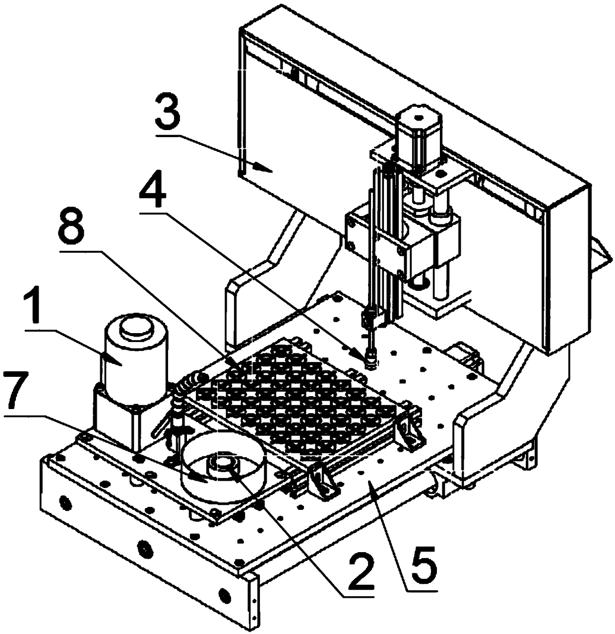
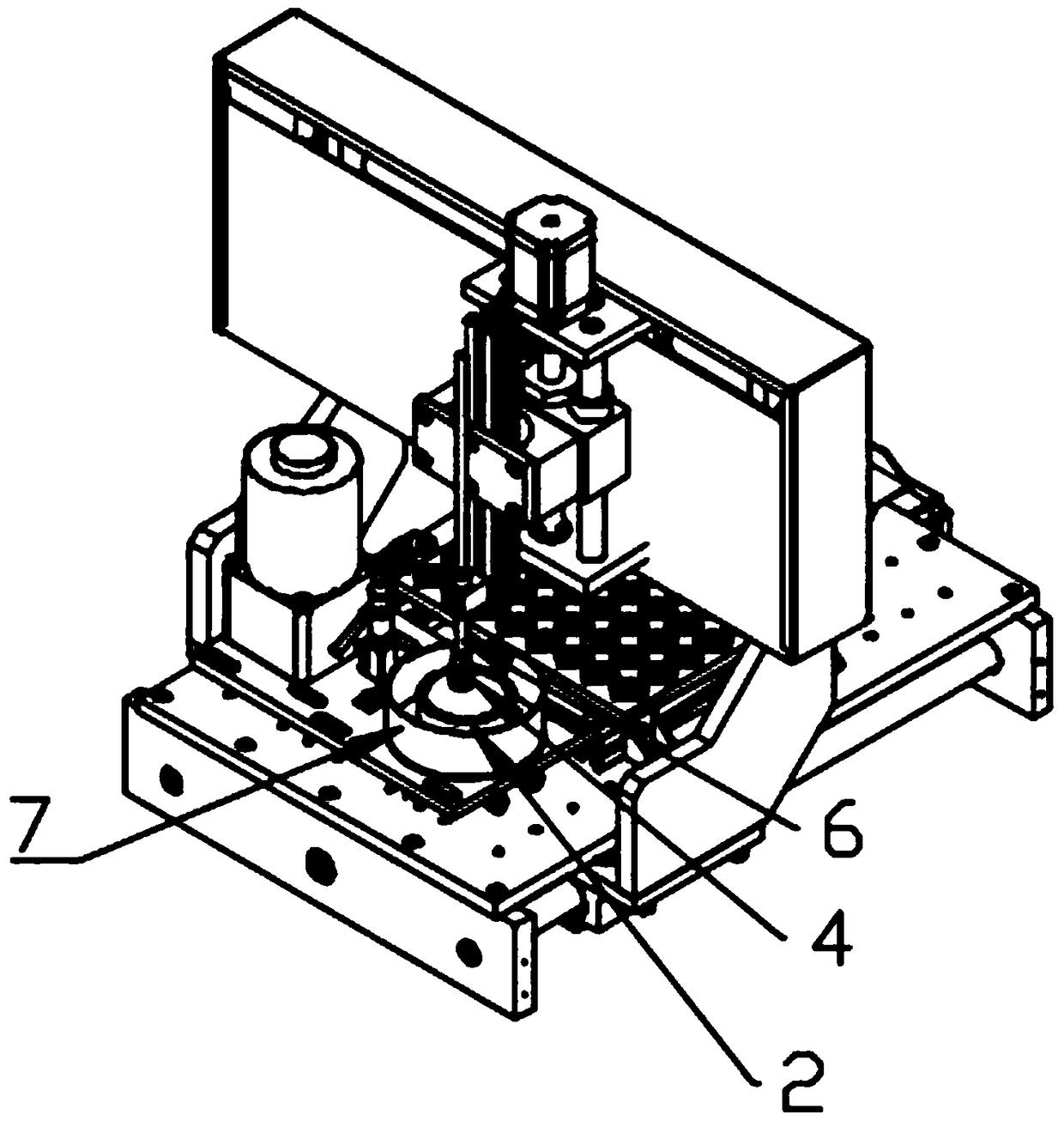
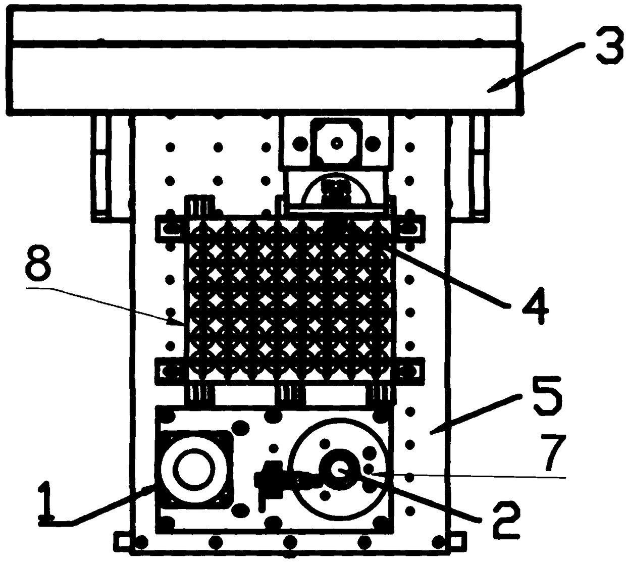
[0035] Such as Figures 1 to 3 As shown, the automatic chamfering machine of this embodiment includes: a motor, a chamfering die 2, a three-axis moving mechanism 3, a vacuum chuck 4, a working platform 5 and a control system.

[0036] The vacuum chuck is connected to the vacuum generator through a solenoid valve; the solenoid valve is connected to a control system for controlling the tightness of the vacuum chuck. Automatically control the tightness of the vacuum chuck to ensure that the components can be firmly adsorbed and fixed or gently and stably released during the transfer and processing process, ensuring processing stability and precision.

[0037] Such as figure 1 As shown, as a preferred solution, a rectangular template 8 is provided on the working platform, and multiple mold cavities are arranged at equal intervals horizontally and vertically on the template 8, and multiple components are placed in the mold cavities of the template at fixed points. A plurality of ...

Embodiment 2

[0051] Such as Figure 8 and 9 As shown, compared with embodiment 1, an electric turntable 11 is set on the working platform of the present embodiment 1, and a plurality of chamfering molds 2 are evenly arranged on the electric turntable 11, and the first motor 1 driving the chamfering mold rotation is arranged on the electric turntable 11. The bottom of the turntable 11 drives the driving gear 12 to rotate, and the position of the corresponding chamfering mold below the turntable 11 is provided with a passive gear 13, and each chamfering mold 2 is fixedly connected with the passive gear 13 below the turntable 11, when the electric turntable 11 When driven by the servo motor to rotate at a specific angle, one of the driven gears 13 meshes with the driving gear 12, the first motor 1 rotates to drive the driving gear 12 to rotate, and the driving gear 12 drives the engaged passive gear 13 to rotate, and drives the chamfering mold 2 to rotate. The outer side of the turntable 11 ...


PUM


Abstract

The invention discloses an automatic beveling machine. A control system automatically controls a vacuum suction cup on a three-axis moving mechanism to suck components on a working platform to be moved into a chamfering die; two motors drive the components and the chamfering die correspondingly to reversely rotate to polish the components, during polishing, the magnitude of the pressure is controlled through a pressure adjusting spring, and after one of the components is machined, the components are returned back to the original positions; the polishing face of the chamfering die is in a hollow hemisphere shape; and a plurality of mounting hole positions are reserved in the working platform for mounting of different sample plates, and a plurality of die holes which are formed according toa certain rule are formed in the sample plates for fixed placement of the components. According to the automatic beveling machine, automation can be achieved, the working efficiency is improved greatly, and the machining intensity of workers is reduced; and the appropriate pressure can be controlled through the pressure adjusting spring, the chamfering die of a spherical structure can ensure thatthe chamfered angle of a product is 45 degrees, force bearing and beveling are more uniform, and thus the automatic beveling machine is suitable for beveling of the different components and high in applicability.

Description

technical field [0001] The invention belongs to the technical field of component processing, and in particular relates to an automatic edge beveling machine. Background technique [0002] Optical components or wafers need to be ground and chamfered during the production process to remove the machining allowance and sharp corners of the outer edge. In the traditional beveling processing process, hand-held components are usually used to process on the beveling grinding wheel. Manual bevelling is time-consuming, laborious, inefficient, and the manual operation has poor stability and large errors, resulting in the processing accuracy of the same batch of products. And the consistency is poor, especially for some components that require specific angle chamfering. The existing grinding machine has a single point of force during grinding and cannot accurately control the grinding pressure; for some components with relatively low mechanical strength, if the grinding pressure is not...

Claims


Application Information

Patent Timeline
Patent Type & Authority Applications(China)
IPC IPC(8): B24B9/06B24B41/06B24B55/06B24B49/16B24B47/12B24B27/00
CPCB24B9/065B24B27/00B24B41/068B24B47/12B24B49/16B24B55/06
Inventor 肖志权贺鹏李学雷
Owner UNION OPTIC
Why Eureka
Try Eureka