A selective laser melting additive manufacturing equipment

A technology of selective laser melting and additive manufacturing, which is applied in the directions of additive manufacturing, additive processing, and process efficiency improvement, and can solve the problems of insufficient forming efficiency of SLM technology.

Active Publication Date: 2021-07-06
SHANTOU UNIV
View PDF0 Cites 0 Cited by
  • Summary
  • Abstract
  • Description
  • Claims
  • Application Information

AI Technical Summary

Problems solved by technology

[0005] The purpose of the present invention is to provide a selective laser melting additive manufacturing equipment to solve the problems of insufficient forming efficiency of the existing SLM technology; to significantly improve the efficiency of the selective laser melting equipment

Method used


Image

  • A selective laser melting additive manufacturing equipment
  • A selective laser melting additive manufacturing equipment
  • A selective laser melting additive manufacturing equipment

Examples


Embodiment 1

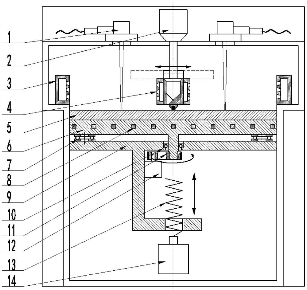
[0025] Laser melting additive manufacturing equipment of the present invention such as figure 1 shown. The equipment includes a point heat source laser vibrating mirror system 1; a powder supply system 2, a powder spreading device 4, a forming workbench system, and a smoke and dust circulation system.

[0026] The forming table system includes a base plate 5, a movable base 6, a thrust ball bearing 7, a preheating device 8, a fixed base 9, an angular contact ball bearing 10, a pulley mechanism 11, a small servo motor 12, a screw mechanism 13, Large Servo Motor14. The substrate 5 is fixed on the movable abutment 6; the movable abutment 6 is fixed on the fixed abutment 9 through a thrust ball bearing 7; the angular contact ball bearing 10 is connected with the movable abutment 6, and the small servo motor 12 passes through the angular contact ball The bearing 10 and the pulley mechanism 11 drive the movable base 6 to rotate at a uniform speed. The screw mechanism 13 is connec...

Embodiment 2

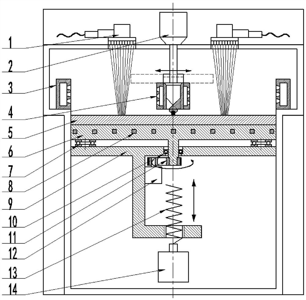
[0033] The selective laser melting additive manufacturing equipment of the present invention is as figure 2 shown. The equipment includes a line heat source laser vibrating mirror system 1; a powder supply system 2, a powder spreading device 4, a forming workbench system, and a smoke and dust circulation system.

[0034] The forming table system includes a base plate 5, a movable base 6, a thrust ball bearing 7, a preheating device 8, a fixed base 9, an angular contact ball bearing 10, a pulley mechanism 11, a small servo motor 12, a screw mechanism 13, Large Servo Motor14. The substrate 5 is fixed on the movable abutment 6; the movable abutment 6 is fixed on the fixed abutment 9 through a thrust ball bearing 7; the angular contact ball bearing 10 is connected with the movable abutment 6, and the small servo motor 12 passes through the angular contact ball The bearing 10 and the pulley mechanism 11 drive the movable base 6 to rotate at a uniform speed. The screw mechanism ...


PUM


Abstract

The invention relates to a selective laser melting additive manufacturing equipment, comprising a laser galvanometer system, a powder supply system, a powder spreading device, a forming workbench system, and a smoke and dust circulation filtering system; the powder spreading device comprises a powder spreading scraper and an accelerated smoke blowing mechanism; The accelerated smoke blowing mechanism is symmetrically arranged on both sides of the powder-spreading scraper; the powder-spreading scraper adopts a symmetrical reverse design; the forming table system includes a base plate, a movable abutment, a thrust ball bearing, a preheating device, a fixed abutment, and a rotating device , vertical up and down movement device; preheating device is arranged inside the movable base; powder supply system is located above the powder spreading device; powder spreading device is located just above the midline of the substrate; Symmetrically distributed at both ends of the powder spreading device. The invention greatly shortens the waiting time for powder spreading, and the invention also introduces a line laser heat source, which can increase the forming efficiency of the laser additive manufacturing equipment dozens of times. Especially suitable for high-efficiency forming of complex metal parts.

Description

technical field [0001] The invention belongs to metal laser additive manufacturing, in particular to a selective laser melting additive manufacturing equipment. Background technique [0002] Selective Laser Melting (SLM) technology belongs to the rapid solidification manufacturing process. It is one of the most cutting-edge and most promising metal additive manufacturing technologies that emerged in the 1990s. The strategic commanding heights that the country is actively seizing will bring about comprehensive and profound changes in the entire manufacturing system. Developed countries such as Europe and the United States have even raised it to the national strategic level of "reindustrialization", "recapturing manufacturing", and "reviving the economy", and have formulated industrial policies for additive manufacturing, taking it as the core of enhancing national competitiveness One of the techniques. It was originally developed by Dr. M. Fockele et al. as a way to form de...

Claims


Application Information

Patent Timeline
Patent Type & Authority Patents(China)
IPC IPC(8): B22F3/105B33Y30/00
CPCB33Y30/00B22F10/00B22F10/36B22F12/49B22F10/28B22F12/90B22F12/44B22F12/52B22F12/10B22F12/67B22F12/37B22F10/77Y02P10/25
Inventor 毛忠发牛小东魏华贤吴福培陈新辉
Owner SHANTOU UNIV
Why Eureka
Try Eureka