
Article clamping device of automatic paint spraying equipment

A technology of spraying equipment and object clips, applied in the direction of spraying devices, etc., can solve the problems of inability to reduce indoor air pollution, no filtration, special attention to safety, avoid inhalation and skin contact, etc., to reduce indoor air pollution and improve painting efficiency. , the effect of good use of foreground

Inactive Publication Date: 2019-02-15
合肥金新允电子技术有限公司
View PDF9 Cites 1 Cited by
  • Summary
  • Abstract
  • Description
  • Claims
  • Application Information

AI Technical Summary

Problems solved by technology

[0002] Spray paint is a kind of artificial paint, made of nitrocellulose, resin, pigment, solvent, etc., usually sprayed evenly on the surface of the object with a spray gun, water resistant, oil resistant, fast drying, used to paint cars, aircraft, wood, Leather, etc. This substance is toxic and has certain effects on the body. Different brands of spray paint have different toxicity due to different component contents. Special attention should be paid to safety when using, and avoid inhalation and skin contact. Clamping to play a stable role to prevent shaking during processing operations and thus affect the quality of painting; the existing painting clamping device has certain disadvantages in use, does not have the function of clamping and rotating, and cannot cooperate with daily painting operations , and does not have the function of filtering, and cannot reduce indoor air pollution, which has brought a certain impact in actual use. Therefore, we propose an object holding device for automatic painting equipment

Method used


Image

  • Article clamping device of automatic paint spraying equipment
  • Article clamping device of automatic paint spraying equipment
  • Article clamping device of automatic paint spraying equipment

Examples


Embodiment Construction

[0018] In order to make the technical means, creative features, goals and effects achieved by the present invention easy to understand, the present invention will be further described below in conjunction with specific embodiments.

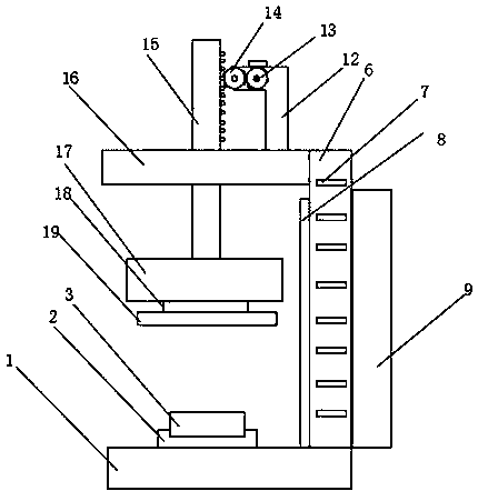
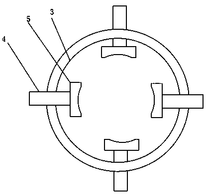
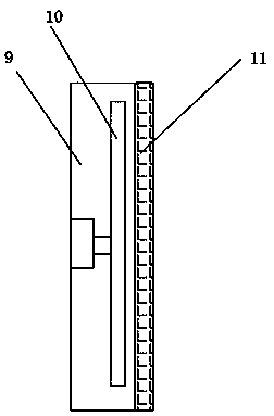
[0019] Such as Figure 1-3 As shown, an object clamping device for automatic painting equipment includes a supporting base 1, a rotating shaft seat 2 is fixedly installed on the outer surface of the upper end of the supporting base 1, and a suiting seat 3 is placed inside the rotating shaft seat 2, and the suiting seat 3 The inner surface of the threaded rod 4 is rotatably installed with a threaded rod 4, and the outer surface of the threaded rod 4 is rotatably installed with a fastener 5, and the upper end outer surface of the support base 1 is welded with a device casing 6, and the front end outer surface of the device casing 6 is welded. A maintenance handle 7 is installed, an air inlet 8 is provided on one side outer surface of the device casi...


PUM


Abstract

The invention discloses an article clamping device of automatic paint spraying equipment. The article clamping device comprises a supporting base. A rotation shaft base is fixedly arranged on the outer surface of the upper end of the supporting base, a sleeving base is arranged in the rotation shaft base, a threaded rod is rotationally arranged on the inner surface of the sleeving base, and a fastener is rotationally arranged on the outer surface of the threaded rod. A device machine shell is welded and installed on the outer surface of the upper end of the supporting base. A maintaining handle is welded and installed on the outer surface of the front end of the device machine shell. An air inlet is formed in the outer surface of one side of the device machine shell, and an induced draft fan is arranged on the outer surface of the other side of the device machine shell and internally provided with a fan. A filter net is arranged on the outer surface of one side of the induced draft fan, and a strengthening table is welded and installed on the outer surface of the device machine shell. The article clamping device of the automatic paint spraying equipment has the function of clampingand rotating, daily paint spraying work can be convenient, meanwhile, the filter function is achieved, indoor air pollution is reduced, and better usage prospects are brought.

Description

technical field [0001] The invention relates to the field of painting clamping, in particular to an object clamping device of automatic painting equipment. Background technique [0002] Spray paint is a kind of artificial paint, made of nitrocellulose, resin, pigment, solvent, etc., usually sprayed evenly on the surface of the object with a spray gun, water resistant, oil resistant, fast drying, used to paint cars, aircraft, wood, Leather, etc. This substance is toxic and has certain effects on the body. Different brands of spray paint have different toxicity due to different component contents. Special attention should be paid to safety when using, and avoid inhalation and skin contact. Clamping to play a stable role to prevent shaking during processing operations and thus affect the quality of painting; the existing painting clamping device has certain disadvantages in use, does not have the function of clamping and rotating, and cannot cooperate with daily painting operat...

Claims


Application Information

Patent Timeline
Patent Type & Authority Applications(China)
IPC IPC(8): B05B13/02B05B14/00
CPCB05B13/0228B05B13/0285B05B14/00
Inventor 贾中全杜立村
Owner 合肥金新允电子技术有限公司
Learn More