Photoelectric hybrid cable for small base stations

A technology of photoelectric hybrid cable and small base station, which is applied in the direction of power cables, insulated cables, and power cables including optical transmission components, etc., which can solve the problems of on-site termination, low cost and laying efficiency, difficult network monitoring and management, and large transmission loss, etc. Problems, to meet the equipment connection requirements, fast and easy networking, small size effect

Pending Publication Date: 2019-02-12
JIANGSU ZHONGTIAN TECH CO LTD
View PDF0 Cites 2 Cited by
  • Summary
  • Abstract
  • Description
  • Claims
  • Application Information

AI Technical Summary

Problems solved by technology

The optical-electrical hybrid cable for RRU in YD / T 2289.3 is suitable for indoor and outdoor short-distance vertical deployment. It uses tight-buffered optical fiber as the optical unit, and has no advantages in field termination, cost, and laying efficiency.
The indoor distributed antenna system uses the feeder line, which has large size, complex lines, difficult network monitoring and management, and large transmission loss at medium and high frequencies

Method used


Image

  • Photoelectric hybrid cable for small base stations
  • Photoelectric hybrid cable for small base stations
  • Photoelectric hybrid cable for small base stations

Examples


Embodiment 1

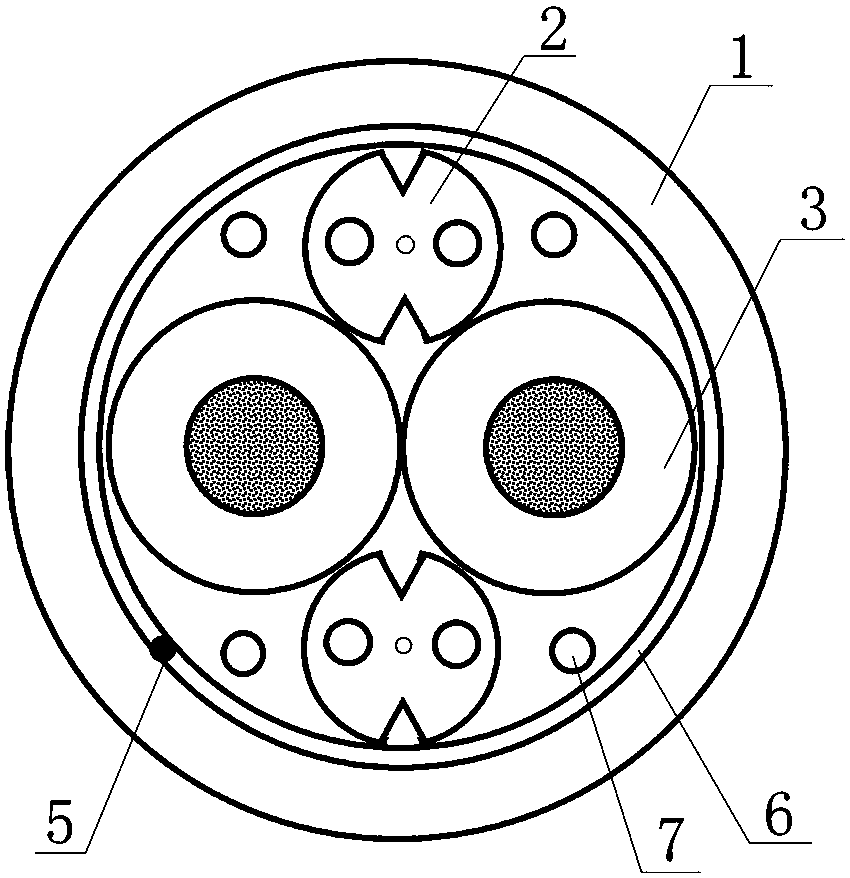
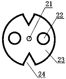
[0028] Such as figure 1 As shown, a photoelectric hybrid cable for a small base station of the present invention includes an outer sheath 1, two butterfly optical cables 2 and two power cords 3, the two power cords 3 are arranged side by side, and a butterfly optical cable 2 is arranged on One side of the two power cords 3 is located in the depression of the contact parts of the two power cords 3, and the other butterfly cable 2 is arranged on the other side of the two power cords 3 and located in the depression of the contact parts of the two power cords 3, The outer sheath 1 covers the outer sides of the two butterfly cables 2 and the two power cables 3 .

[0029] An optoelectronic hybrid cable for small base stations also includes a tearing rope 5 , and the tearing rope 5 is arranged inside the outer sheath 1 . A tape layer 6 is arranged inside the outer sheath 1, and the tape layer 6 is made of water blocking tape, polyester tape or aluminum-plastic composite tape. A fil...

Embodiment 2

[0034] Such as figure 1 As shown, a photoelectric hybrid cable for a small base station of the present invention includes an outer sheath 1, two butterfly optical cables 2 and two power cords 3, the two power cords 3 are arranged side by side, and a butterfly optical cable 2 is arranged on One side of the two power cords 3 is located in the depression of the contact parts of the two power cords 3, and the other butterfly cable 2 is arranged on the other side of the two power cords 3 and located in the depression of the contact parts of the two power cords 3, The outer sheath 1 covers the outer sides of the two butterfly cables 2 and the two power cables 3 .

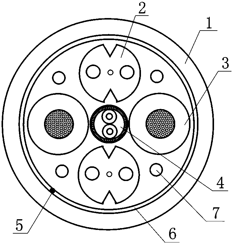
[0035] A photoelectric hybrid cable for small base stations also includes at least one twisted pair 4 for controlling and managing the wireless radio remote unit. Such as Figure 5 As shown, the twisted pair 4 includes two twisted insulated wires and an aluminum foil 41, the aluminum foil 41 is coated on the outside of ...


PUM


Abstract

The invention discloses a photoelectric hybrid cable for small base stations, which comprises an outer sheath, two butterfly optical cables and two power wires. The two power wires are arranged in parallel; one butterfly optical cable is arranged on one side of the two power wires in a recess of the contact part of the two power wires, and the other butterfly optical cable is arranged on the otherside of the two power wires in the recess of the contact portion of the two power wires; the two butterfly optical cables and the two power wires are covered with the outer sheath. The photoelectrichybrid cable is suitable quickly and simply deploying 4G and 5G small base station networks, and allows digital coverage of indoor wireless signals and dense coverage of outdoor wireless signals.

Description

technical field [0001] The invention relates to a photoelectric hybrid cable, in particular to a photoelectric hybrid cable for a small base station. Background technique [0002] With the maturity of 4G technology and the development of 5G technology, more and more small base stations are used for wireless signal coverage in the field of wireless communication. At this time, a photoelectric hybrid cable is needed to connect the baseband processing unit and Radio frequency remote unit. At present, macro base stations are used for outdoor wireless signal coverage, and photoelectric hybrid cables for wireless radio remote units as specified in YD / T 2289.3 are used in macro base stations. This product uses tight-sleeved optical fibers as optical units; indoor wireless signal coverage A distributed antenna system is used, and a feeder is used in a distributed antenna system. This product has a large size and has a large transmission loss at medium and high frequencies. The op...

Claims


Application Information

Patent Timeline
Patent Type & Authority Applications(China)
IPC IPC(8): H01B9/00H01B9/02H01B7/04H01B7/02H01B7/17H01B7/282H01B7/285H01B7/295H01B7/38G02B6/44
CPCH01B7/02H01B7/0216H01B7/04H01B7/17H01B7/2825H01B7/285H01B7/295H01B7/385H01B9/003H01B9/005H01B9/024G02B6/4433G02B6/566
Inventor 淦韦李强赵静尹同同李新建缪小明
Owner JIANGSU ZHONGTIAN TECH CO LTD
Why Eureka
Try Eureka