
Flameless combustion system and method for low-calorific-value fuel gas

A flameless combustion, low calorific value technology, applied in the direction of combustion methods, gas fuel burners, burners, etc., can solve the problems of increasing accidental risks, unfavorable equipment modification, complex equipment, etc., to improve energy utilization efficiency and structural safety Reliable, locally produced results

Active Publication Date: 2019-02-12
TIANJIN UNIV
View PDF4 Cites 1 Cited by
  • Summary
  • Abstract
  • Description
  • Claims
  • Application Information

AI Technical Summary

Problems solved by technology

[0006] It should be pointed out that when the heat storage body is used for heat storage, the gas may be cracked due to the high preheating temperature of the gas, which will have a certain impact on the combustion system, and may cause gas leakage at the moment of gas reversing, increasing the The risk of accidents is reduced, and the heat storage body is used for combustion, the equipment is relatively complicated, and it is not conducive to the transformation of the original equipment or traditional communication equipment.
In addition, the combustion system that simply preheats the furnace will cause a lot of heat to be taken away by the high-temperature flue gas, and the energy will not be fully utilized.

Method used


Image

  • Flameless combustion system and method for low-calorific-value fuel gas
  • Flameless combustion system and method for low-calorific-value fuel gas
  • Flameless combustion system and method for low-calorific-value fuel gas

Examples


Embodiment 1

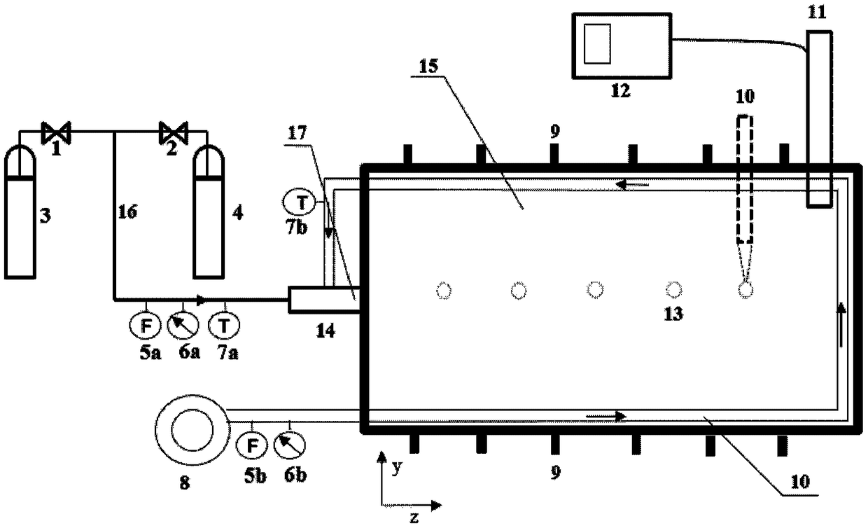
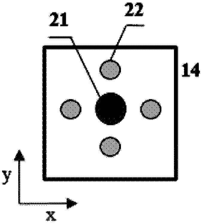
[0046] Such as Figure 1~3 As shown, in the flameless combustion system for low calorific value gas in this embodiment, the high calorific value gas preheats the furnace assembly: the high calorific value gas cylinder 3 provides high calorific value gas, the valve 1 controls the high calorific value gas to enter the gas pipeline 16, and the gas pipeline Flowmeter 5a, pressure gauge 6a, thermometer 7a are arranged in sequence on 16, high calorific value gas 3 enters burner 14 with electric spark igniter 17 together with the air in air cooling pipe 10, and burner 14 is connected with cuboid furnace 15 , The upper part of the furnace tail is provided with a flue gas outlet 11. Air cooling pipe preheating air assembly: fan 8 provides air at normal temperature, followed by air cooling pipe 10, where air cooling pipe 10 does not enter the furnace section, flow meter 5b, pressure gauge 6b, thermometer 7b are arranged in sequence, and air cooling pipe 10 enters furnace chamber 15 Go ...


PUM


Abstract

The invention provides a flameless combustion system for low-calorific-value fuel gas. The system comprises a hearth, a fuel gas pipeline, a high-calorific-value fuel gas preheating hearth assembly, an air cooling tube preheating air assembly, and a low-calorific-value fuel gas flameless combustion assembly, wherein a burner with an igniter is arranged at the head part of the hearth, the fuel gaspipeline is connected to the burner, and is used for conveying high-calorific-value fuel gas and / or the low-calorific-value fuel gas, the high-calorific-value fuel gas preheating hearth assembly comprises a high-calorific-value fuel gas supplying device connected to the fuel gas pipeline and used for supplying the high-calorific-value fuel gas, the air cooling tube preheating air assembly comprises an air supplying device and an air cooling tube, the air supplying device is used for supplying the normal-temperature air, the air cooling tube is arranged between the air supplying device and theburner, the middle section of the air cooling tube extends into the hearth along the inner wall of the hearth to preheat the normal-temperature air in the hearth and then to convey the air to the burner, and the low-calorific-value fuel gas flameless combustion assembly comprises a low-calorific-value fuel gas supplying device connected to the fuel gas pipeline and used for supplying the low-calorific-value fuel gas. According to the system and the method, stable flameless combustion of the low-calorific-value fuel gas is realized; and the system and the method are clean and efficient, and theenergy utilization rate is high.

Description

technical field [0001] The invention relates to the field of gas clean and high-efficiency combustion equipment, in particular to a flameless combustion system and method for low calorific value gas. Background technique [0002] There is no clear concept of low calorific value gas. Generally, gas fuels can be divided into three categories according to their own calorific value. The calorific value is greater than 15.07MJ / Nm 3 The high calorific value fuel, the calorific value is 6.28 ~ 15.07MJ / Nm 3 The fuel is medium calorific value, and the calorific value is less than 6.28MJ / Nm 3 of low calorific value fuel. Common low calorific value gaseous fuels in industry mainly include low calorific value tail gas in chemical process, blast furnace gas, smelting tail gas in petrochemical industry, low concentration coal mine gas, etc. In addition, the H produced by pyrolysis and gasification of biomass 2 , CO, N 2 , CO 2 、CH 4 The combustible gas with the same composition, th...

Claims


Application Information

Patent Timeline
Patent Type & Authority Applications(China)
IPC IPC(8): F23D14/00F23D14/66F23D14/48F23D14/46
CPCF23D14/00F23D14/46F23D14/48F23D14/66Y02E20/34
Inventor 陈冠益周生权颜蓓蓓李远博程占军马文超
Owner TIANJIN UNIV
Learn More