Self-piercing rivet die

A technology of self-piercing riveting and mold, which is applied in the direction of rivets, screws, connecting components, etc., and can solve problems such as the weakening of self-piercing rivet connections

Active Publication Date: 2019-02-05
BOLLHOFF VERBINDUNGSTECHNIK GMBH
View PDF13 Cites 0 Cited by
  • Summary
  • Abstract
  • Description
  • Claims
  • Application Information

AI Technical Summary

Problems solved by technology

Usually this is not achieved, which leads to a weakening of the self-piercing rivet joint

Method used


Image

  • Self-piercing rivet die
  • Self-piercing rivet die
  • Self-piercing rivet die

Examples


example 1

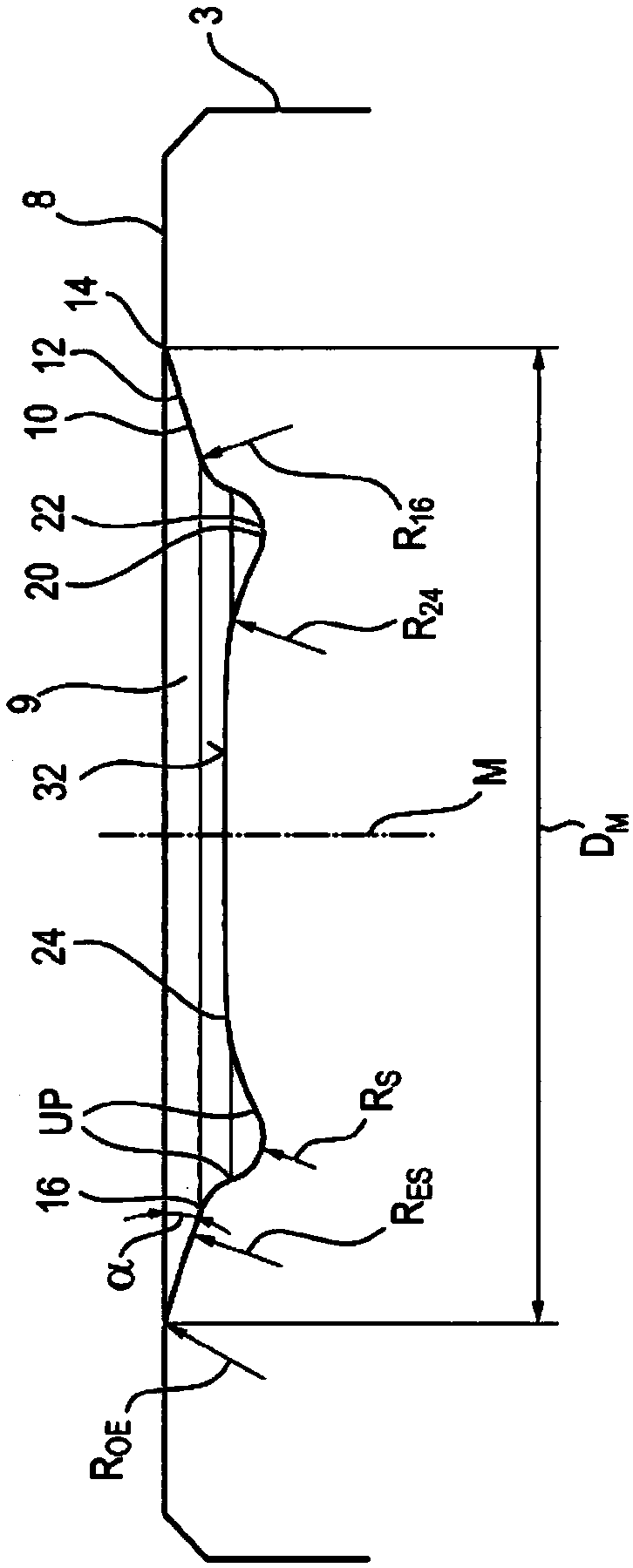
[0066] similar to image 3 The mold form of , with the following geometric data

[0067] D. M =12.2mm

[0068] D. 20 =8.395mm

[0069] ∝=18°

[0070] R OE =0.5mm

[0071] R ES =10.4mm

[0072] R S =0.2mm

[0073] R 24=11.17mm

[0074] R 16 =0.6mm

[0075] T RK =0.9mm

example 2

[0077] similar to image 3 The mold form of , with the following geometric data

[0078] D. M =12.2mm

[0079] D. 20 =7.3mm

[0080] ∝=18°

[0081] R OE =0.5mm

[0082] R ES =10.4mm

[0083] R S =0.8mm

[0084] R 24 =1.44mm

[0085] R 16 =0.6mm

[0086] T RK =1.3mm

example 3

[0088] similar to Figure 9 The mold form of , with the following geometric data

[0089] D. M =12.2mm

[0090] D. 20 =8.395mm

[0091] ∝=18°

[0092] R OE =0.5mm

[0093] R ES =10.4mm

[0094] R S =0.2mm

[0095] R 24 =11.17mm

[0096] R 16 =0.6mm

[0097] T RK =0.9mm

[0098] D. A =3.6mm

[0099] T A =0.9mm


PUM

PropertyMeasurementUnit
depthaaaaaaaaaa
diameteraaaaaaaaaa

Abstract

The present invention describes a self-piercing rivet die for a rivet gun, by which die a self-piercing rivet connection can be produced in a plurality of components by formation of a closing head. This self-piercing rivet die (1) is characterised by a main body (3) with a top face (8) and a recess (9) which is formed thereon and is arranged rotationally symmetrically relative to a central axis Mof the self-piercing rivet die 1. In the cross-section of the self-piercing rivet die (1) the recess (9) has a draft angle (12) of the draft section (10) which merges radially via a step (16) into anarcuate depression (22) of the annular channel section (20), wherein radially inwards the arcuate depression (22) rises in a rectilinear or arcuate or curvilinear manner to the die base (30).

Description

1. Technical field [0001] The invention relates to a self-piercing rivet die for setting self-piercing rivets on at least first and second parts, a mounting device combined with the self-piercing rivet die, through which the self-piercing rivet die is formed in at least two A connection established between components, and a method for establishing this connection. 2. Background of the invention [0002] In the prior art it is known to join at least first and second parts by means of self-pierce riveting. For this purpose, the self-piercing rivet is driven by a mounting device to at least two parts, wherein the at least two parts are supported on a die arranged opposite the punch. Due to its shape, this mold affects the characteristics of the joint connection. [0003] For example, DE 199 05 528 B4 discloses an anvil mold which is characterized by a flat surface which serves as a seat for supporting the parts to be joined. The die formed in this manner provides an aestheti...

Claims


Application Information

Patent Timeline
Patent Type & Authority Applications(China)
IPC IPC(8): B21J15/02B21J15/36
CPCB21J15/025B21J15/36F16B19/086F16B19/10
Inventor 丹尼斯·亨克丹尼尔·荣克维茨安德烈亚斯·马克思克斯弗朗茨-费迪南·门恩
Owner BOLLHOFF VERBINDUNGSTECHNIK GMBH
Why Eureka
Try Eureka