
Powertrain mount structure of vehicle

A powertrain and vehicle technology, applied in the direction of power devices, vehicle components, transmission parts, etc., can solve the problem of lowering the rigidity of the vehicle body

Active Publication Date: 2019-02-05
MAZDA MOTOR CORP
View PDF8 Cites 0 Cited by
  • Summary
  • Abstract
  • Description
  • Claims
  • Application Information

AI Technical Summary

Problems solved by technology

[0009] However, in the conventional structure disclosed in Patent Document 2, there is a problem that the rigidity of the vehicle body is lowered due to the formation of the above-mentioned elongated hole.

Method used


Image

  • Powertrain mount structure of vehicle
  • Powertrain mount structure of vehicle
  • Powertrain mount structure of vehicle

Examples


Embodiment Construction

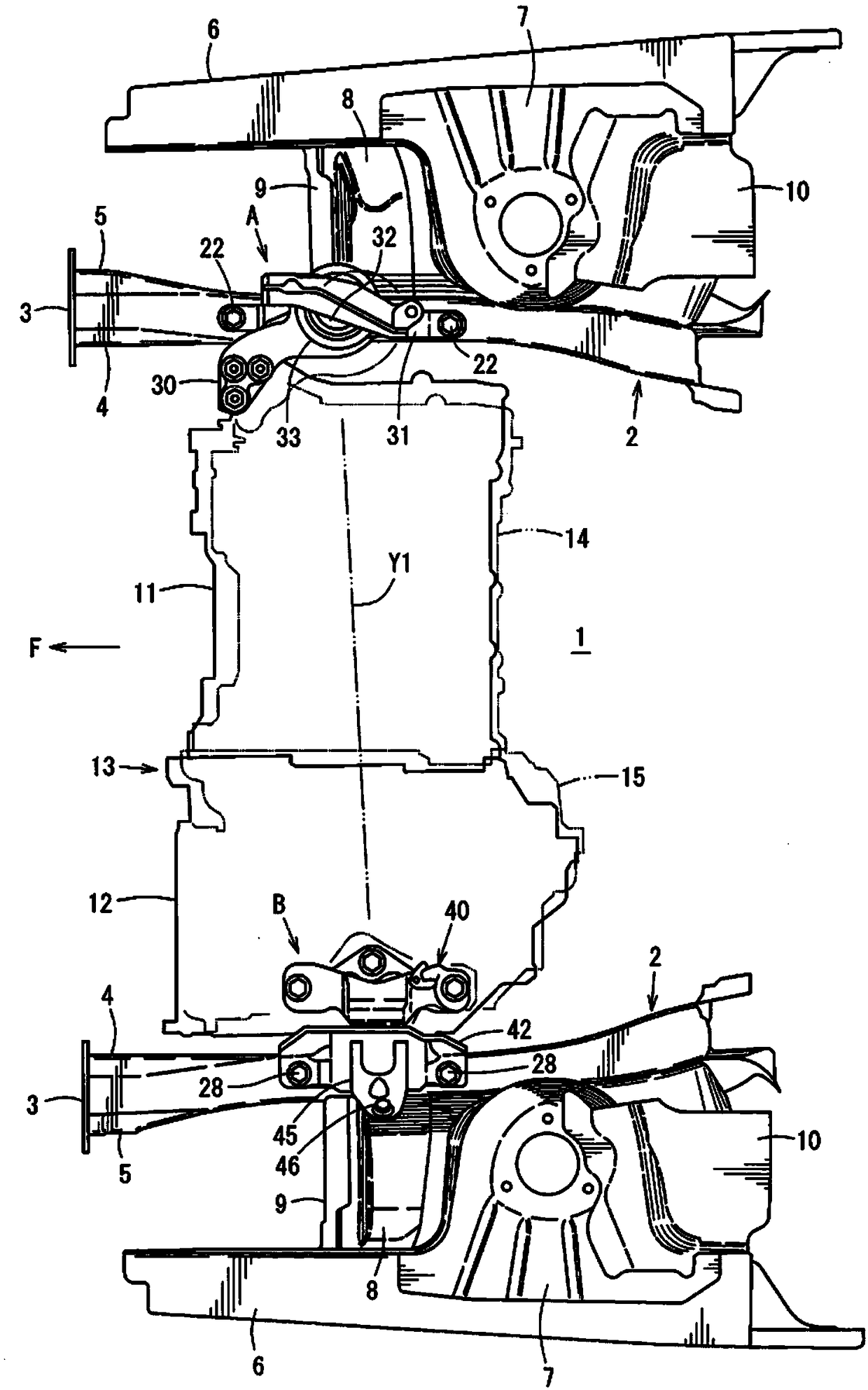
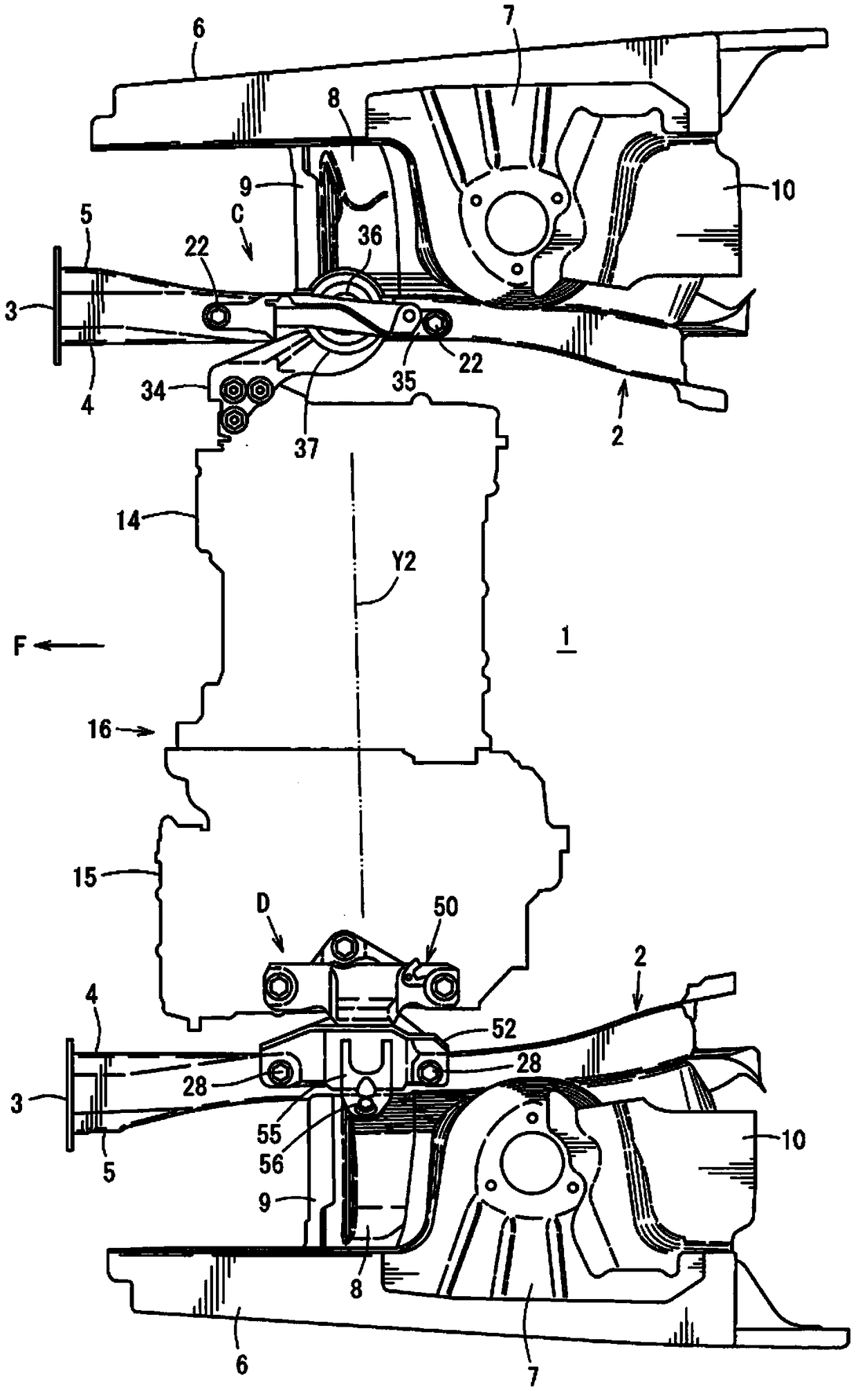
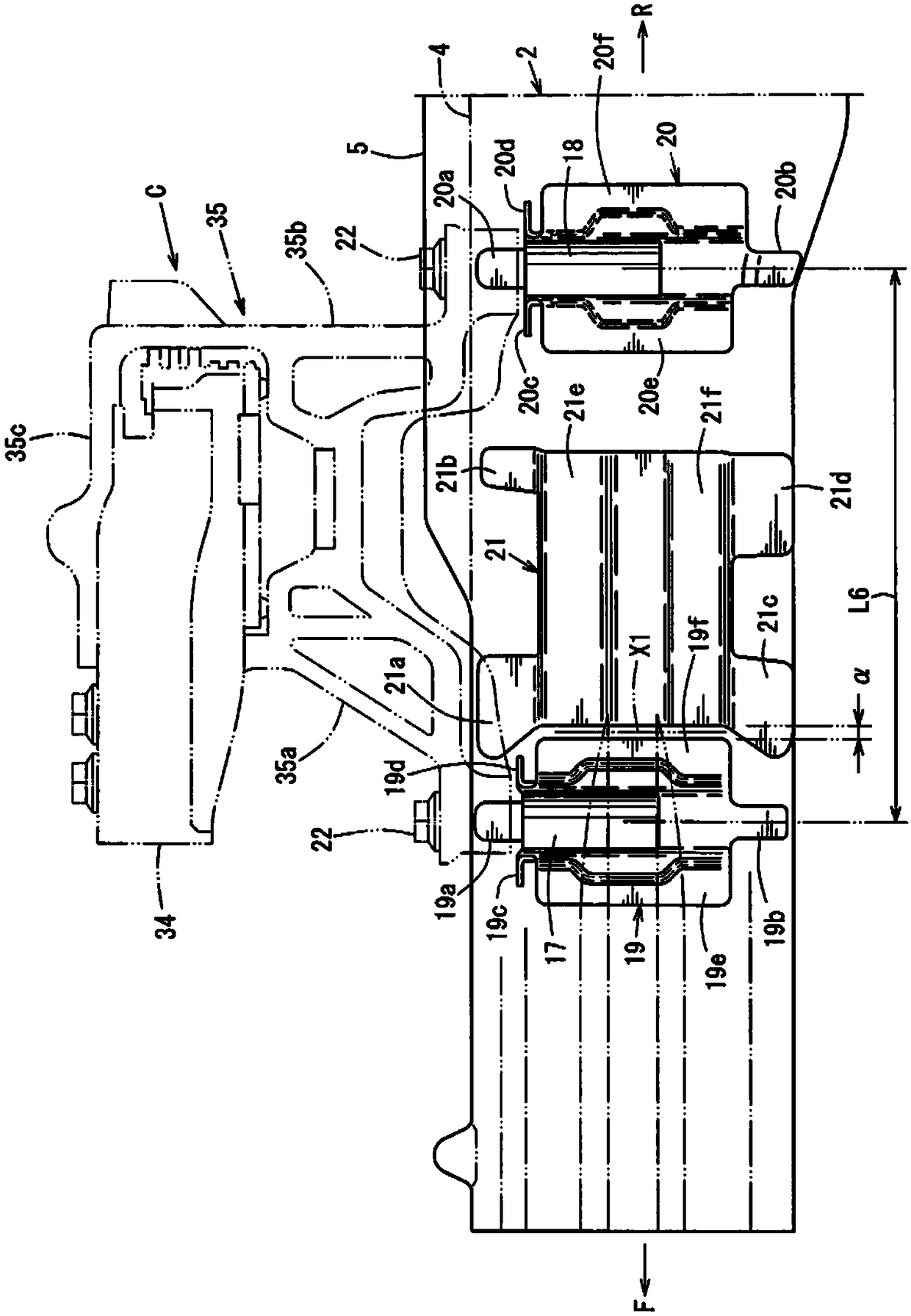
[0044] In order to adjust the position of the elastic roller of the powertrain without reducing the rigidity of the vehicle body, the powertrain assembly structure of the vehicle of the present invention has: left and right front side frames along the front-rear direction of the vehicle on the left and right sides of the engine compartment Extension: the first assembly supporting part, including the first assembly pad and the first assembly bracket holding the first assembly pad, the first assembly bracket is opposite to one of the front side frames of the left and right front frames A plurality of mounting points are provided at intervals in the front and rear, and the powertrain is mounted to the one front side frame through the first mounting bracket via the first mounting rubber pad; and the second mounting support part includes a second mounting A rubber pad and a second mounting bracket holding the second mounting rubber pad. The second mounting bracket is provided with a...


PUM


Abstract

The invention provides a powertrain mount structure of a vehicle, capable of performing positional adjustment of an elastic roller of the powertrain withnot reducing the rigidity of the vehicle body.The powertrain mount structure comprises mount support portions (A, B) to attach a powertrain (13) to a pair of right-and-left front side frames (2), wherein the mount support portions (A, B) includemount rubbers (32, 33) and mount brackets (30, 31, 42), respective longitudinal distances between plural attaching points of the right-and-left vehicle-body-side mount brackets (32, 33) are set to belonger than those of the right-and-left mount rubbers, and the mount rubbers (32, 33) are configured such that longitudinal positions thereof are changeable in a range between the plural attaching points of the mount brackets (31, 42).

Description

technical field [0001] The present invention relates to a powertrain assembly structure of a vehicle. In the powertrain assembly structure of a vehicle, left and right front side frames extending in the front-rear direction of the vehicle are provided on the left and right sides of the engine compartment. The side frame is provided with an assembly support portion for assembly and support of the power assembly. Background technique [0002] In general, a powertrain includes an engine and a transmission, and the powertrain is mounted and supported by left and right front side frames serving as vehicle body strength members via mounting support portions. [0003] In addition, the above-mentioned assembly support part is equipped with assembly rubber pads and assembly brackets, and the elastic roller of the power assembly determined by the rigidity of the assembly pad and the assembly support position is inconsistent with the inertial axis determined by the mass distribution of...

Claims


Application Information

Patent Timeline
Patent Type & Authority Applications(China)
IPC IPC(8): B60K5/12B60K17/06
CPCB60K5/12B60K5/1208B60K17/06B62D25/082B60K5/1216B60K5/04B60Y2306/01B60K5/1283B62D21/02B62D21/09B62D21/152F16H57/025
Inventor 藤明知岩田强志有田洋介三轮出洋巳
Owner MAZDA MOTOR CORP
Learn More