
Device for automatically grinding and detecting square window of valve sleeve of servo valve

A window device and servo valve technology, applied in the field of electro-hydraulic servo, can solve the problems of difficult manufacturing, high precision requirements, and human factors in the grinding process, so as to improve the grinding accuracy and efficiency and solve the process bottleneck.

Pending Publication Date: 2019-02-05
SHANGHAI HENGTUO HYDRAULIC CONTROL TECH
View PDF0 Cites 2 Cited by
  • Summary
  • Abstract
  • Description
  • Claims
  • Application Information

AI Technical Summary

Problems solved by technology

The electro-hydraulic servo valve is a key component that determines the performance of the electro-hydraulic servo system. Due to its high precision requirements and difficult manufacturing, it cannot be mass-produced at present, and the bottleneck restricting the mass production of electro-hydraulic servo valves is the slide valve grinding process.
The efficiency and quality of sliding valve grinding are strongly dependent on the technical level and in-depth research of the operator, so the human factors in the grinding process are obviously affected

Method used


Image

  • Device for automatically grinding and detecting square window of valve sleeve of servo valve
  • Device for automatically grinding and detecting square window of valve sleeve of servo valve
  • Device for automatically grinding and detecting square window of valve sleeve of servo valve

Examples


Embodiment Construction

[0016] The present invention will be further described below in conjunction with the accompanying drawings and embodiments.

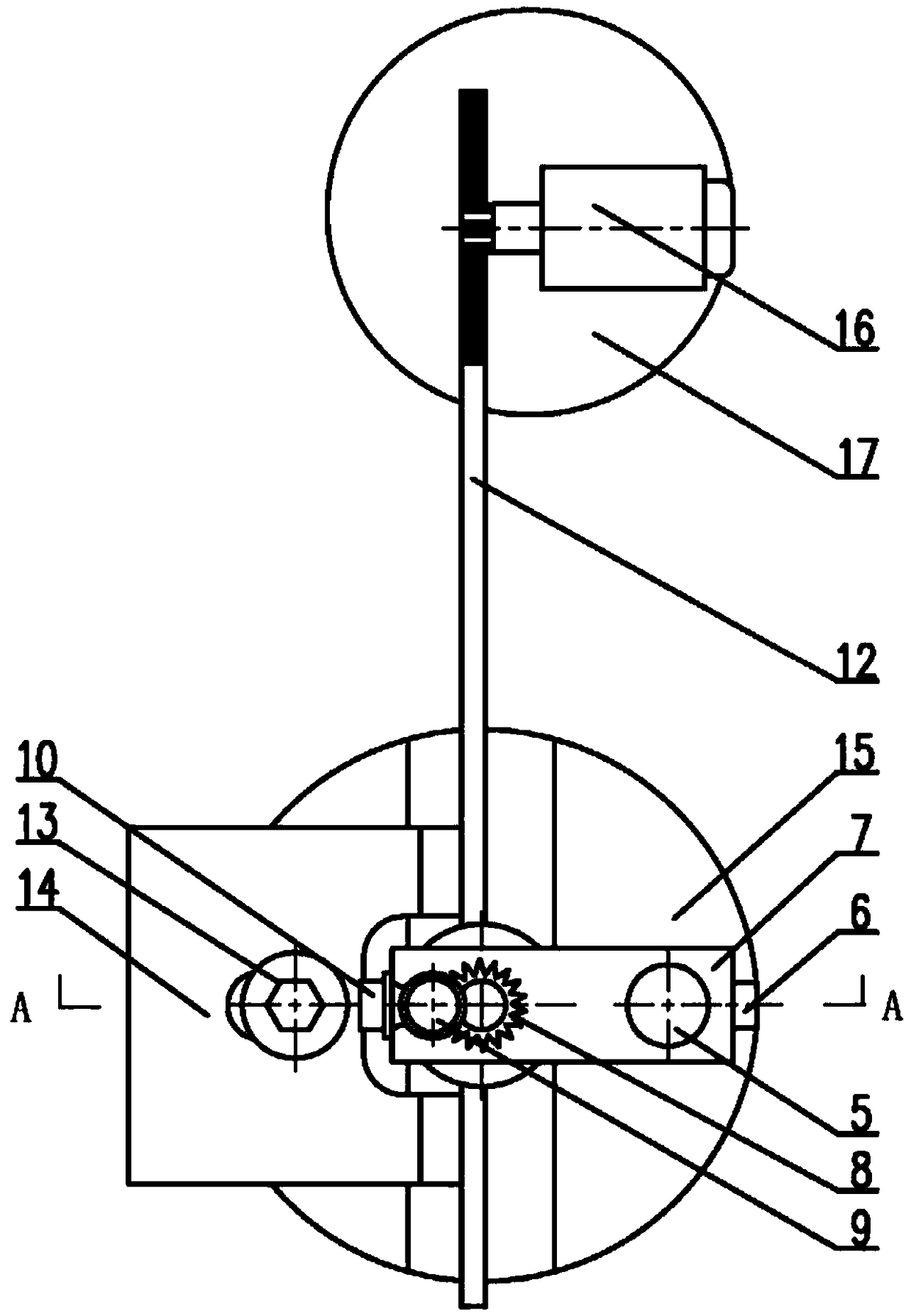
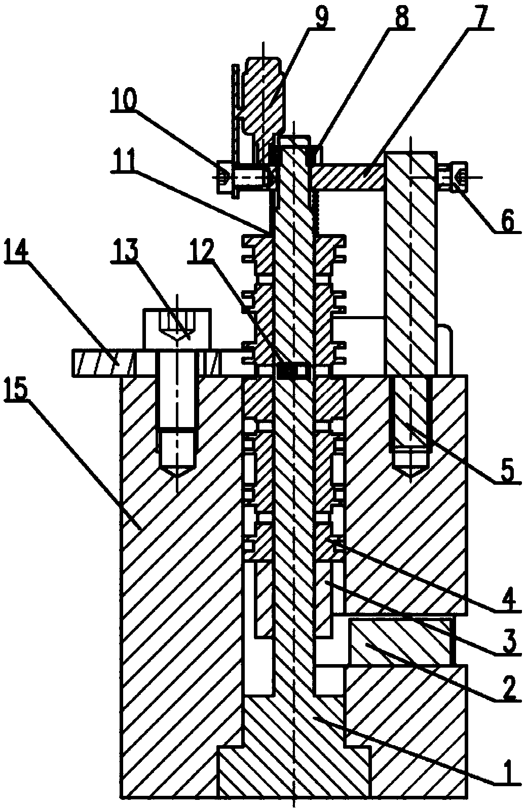
[0017] Such as figure 1 , as shown in 2, an automatic grinding and detection servo valve sleeve square window device, including a mandrel 1, a conversion circuit 2, an LVDT sensor 3, a servo valve sleeve 4, a pillar 5, an M3 screw 6, a pressure plate 7, and an M6 gear Type nut 8, motor one 9, M3.5 screw 10, spring 11, grinding bar 12, M8 screw 13, orientation plate 14, clamp body 15, motor two 16, support table 17, etc. The mandrel 1 is installed in the main hole of the clamp body 15, and fixed through the stepped hole and the M6 ​​gear nut 8; the LVDT sensor 3 and the servo valve sleeve 4 are fixed by gluing the LVDT sensor 3; the conversion circuit 2 and the clamp Specifically, 15 is fixed by buckling; the main hole of the servo valve sleeve 4 is matched with the mandrel 1 through clearance, and a spring 11 is installed between the pressure plate 7 a...


PUM


Abstract

The invention relates to a device for automatically grinding and detecting a square window of a valve sleeve of a servo valve. A central spindle is installed in a main hole of a clamp body and is sleeved with the valve sleeve of the servo valve and an LVDT sensor, the upper end surface of the LVDT sensor is fixedly connected with the lower end face of the valve sleeve of the servo valve, a conversion circuit is arranged in the clamp body corresponding to the LVDT sensor, a strut is fixedly connected to the upper face of the clamp body, one end of a pressure plate is connected to the strut, andthe other end of the pressure plate is connected to the upper part of the central spindle in a sleeving manner; an M-gear type nut is screwed to the upper end of the central spindle and is connectedto the upper plane of the pressure plate, the pressure plate is fixedly connected to a motor 1, and a gear on the first motor is in meshed transmission connection with the M-gear type nut; a spring isconnected between the pressure plate and the valve sleeve of the servo valve; and one end of a grinding bar extends into the square window of the valve sleeve of the servo valve, a rack on the otherend of the grinding bar is in engaged connection with a gear on a second motor. By means of the device, the grinding precision and efficiency can be effectively improved, and a foundation is laid forsolving the bottleneck of a valve sleeve mated grinding process and realizing the mass production of an electro-hydraulic servo valve.

Description

technical field [0001] The invention relates to an electro-hydraulic servo, in particular to a grinding and detection device for the electro-hydraulic servo. Background technique [0002] The electro-hydraulic servo system has a high response frequency, high power-to-weight ratio and torque-to-inertia ratio, and is widely used in control fields such as aviation, aerospace, and ships. The electro-hydraulic servo valve is a key component that determines the performance of the electro-hydraulic servo system. Due to its high precision requirements and high manufacturing difficulty, it cannot be mass-produced at present. The bottleneck restricting the mass production of electro-hydraulic servo valves is the sliding valve grinding process. The efficiency and quality of sliding valve grinding are strongly dependent on the technical level and in-depth research of the operator, so the human factors in the grinding process are obviously affected. Therefore, there is a need for an aut...

Claims


Application Information

Patent Timeline
Patent Type & Authority Applications(China)
IPC IPC(8): B24B37/00B24B37/005B24B37/34
CPCB24B37/00B24B37/005B24B37/34
Inventor 陈冬冬周竹马立瑞余萍方群赵华龙
Owner SHANGHAI HENGTUO HYDRAULIC CONTROL TECH
Learn More