
Novel biliary obstructive liver fibrosis model

A liver fibrosis and obstructive technology, applied in the medical field, can solve the problems of death, rapid increase of intrahepatic bile volume, liver failure in small animals, etc., and achieve good results.

Pending Publication Date: 2019-02-01
SHANGHAI UNIV OF MEDICINE & HEALTH SCI
View PDF0 Cites 0 Cited by
  • Summary
  • Abstract
  • Description
  • Claims
  • Application Information

AI Technical Summary

Problems solved by technology

[0002] The most commonly used method for the bile duct obstructive liver fibrosis model is common bile duct ligation of bile duct obstruction, intraperitoneal injection of chloral hydrate solution for anesthesia, double ligation and separation of free common bile duct after laparotomy, and abdominal cavity suturing, about 4-6 weeks Later, a large number of interlobular bile duct hyperplasia and fibrous tissue hyperplasia can be seen in the portal area, forming portal area-portal area bridging fibrosis, and flaky hepatocyte necrosis can be seen in the liver parenchyma. Cholestasis, increased pressure in the biliary tract, and expansion and rupture of intrahepatic bile ducts may occur. The intrahepatic blood vessels are double oppressed by dilated bile ducts and bile extravasation, resulting in ischemia and necrosis of liver cells, massive proliferation of fibrous tissue, and surrounding hepatic lobules. The disadvantages of this model are as follows: 1. Ligation or cutting of the common bile duct will lead to an excessive increase in the amount of bile in the liver, which cannot simulate and reflect human biliary liver fibrosis objectively; 2. Simple blockade Breaking the common bile duct will lead to liver failure and death in a short period of time in small animals. Therefore, we propose this new model of liver fibrosis with bile duct obstruction

Method used


Image

  • Novel biliary obstructive liver fibrosis model
  • Novel biliary obstructive liver fibrosis model
  • Novel biliary obstructive liver fibrosis model

Examples


Embodiment Construction

[0017] The following will clearly and completely describe the technical solutions in the embodiments of the present invention with reference to the accompanying drawings in the embodiments of the present invention. Obviously, the described embodiments are only some, not all, embodiments of the present invention. Based on the embodiments of the present invention, all other embodiments obtained by persons of ordinary skill in the art without creative efforts fall within the protection scope of the present invention.

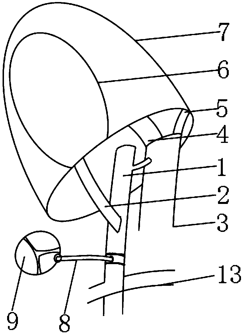
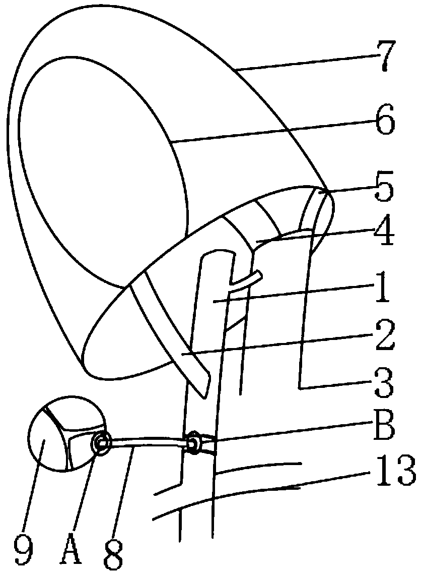
[0018] Such as Figure 1-4 As shown, a new type of bile duct obstructive liver fibrosis model, including the common bile duct 1, is characterized in that: one end of the common bile duct 1 is provided with a cystic duct 2, and one side of the cystic duct 2 is provided with a proper hepatic artery 3. The upper end of the cystic duct 2 is provided with a bile body 6, one end of the common bile duct 1 is provided with a pressure drainage tube 8 on the side close to th...


PUM


Abstract

The invention discloses a novel biliary obstructive liver fibrosis model, which comprises a common bile duct. One end of the common bile duct is provided with a cystic duct; one side of the cystic duct is provided with proper hepatic artery; the upper end of the cystic duct is provided with a gallbladder main body; one side, close to the cystic duct, of one end of the common bile duct is providedwith a pressure drain tube; one end of the pressure drain tube is provided with a tricuspid valve; and a first inner concave clasp is arranged between the tricuspid valve and the pressure drain tube.According to the novel biliary obstructive liver fibrosis model disclosed in the invention, the common bile duct can maintain certain stable inner pressure, clinical obstructive liver fibrosis can bewell simulated, a more effective animal model is provided for treatment of the disease, the pressure of the bile in the liver main body can be controlled, long-term feeding is facilitated, the pathological mechanism and the curative effects of drugs and the like can be observed, and the biliary obstructive liver fibrosis model brings better application prospects.

Description

Technical field: [0001] The invention relates to the medical field, in particular to a novel model of bile duct obstructive liver fibrosis. Background technique: [0002] The most commonly used method for the bile duct obstructive liver fibrosis model is common bile duct ligation of bile duct obstruction, intraperitoneal injection of chloral hydrate solution for anesthesia, double ligation and separation of free common bile duct after laparotomy, and abdominal cavity suturing, about 4-6 weeks Later, a large number of interlobular bile duct hyperplasia and fibrous tissue hyperplasia can be seen in the portal area, forming portal area-portal area bridging fibrosis, and flaky hepatocyte necrosis can be seen in the liver parenchyma. Cholestasis, increased pressure in the biliary tract, and expansion and rupture of intrahepatic bile ducts may occur. The intrahepatic blood vessels are double oppressed by dilated bile ducts and bile extravasation, resulting in ischemia and necrosis...

Claims


Application Information

Patent Timeline
Patent Type & Authority Applications(China)
IPC IPC(8): G09B23/30
CPCG09B23/30
Inventor 辛晓明谢竹青张尹张轩齐潘洲佳
Owner SHANGHAI UNIV OF MEDICINE & HEALTH SCI
Learn More