
Wood die comparison cutting device

A cutting device and mold technology, applied in wood processing equipment, manufacturing tools, special forming/shaping machines, etc., can solve the problems of low manual operation efficiency, unfavorable industrial production, unfavorable pass rate, etc., and improve cutting work Efficiency, expansion of industrial production, and the effect of improving the pass rate

Inactive Publication Date: 2019-02-01
华琳琳
View PDF22 Cites 2 Cited by
  • Summary
  • Abstract
  • Description
  • Claims
  • Application Information

AI Technical Summary

Problems solved by technology

[0003] Wood processing is generally produced in batches. As the basic link of wood cutting in the production process, the basic requirement is to ensure that the cutting error of the same type of wood is within the allowable range. Generally, construction personnel are required to compare the model wood with the processed wood to cut. In this way, the error rate caused by human operation is greater, and at the same time, the work efficiency of manual operation is low, which is not conducive to expanding industrial production and improving the qualified rate. In view of this, the present invention proposes a wood mold comparison cutting device

Method used


Image

  • Wood die comparison cutting device
  • Wood die comparison cutting device
  • Wood die comparison cutting device

Examples


Embodiment Construction

[0023] The technical solution of this patent will be further described in detail below in conjunction with specific embodiments.

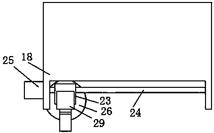
[0024] see Figure 1-3 , a wood mold contrast cutting device, comprising a workbench 1, the workbench 1 is provided with an installation cavity, and the middle part of the top surface of the workbench 1 is fixedly connected with a partition 19, and both sides of the partition 19 are symmetrically provided with a first rotating shaft 2, In addition, the two first rotating shafts 2 are rotatably connected with the workbench 1. The bottom ends of the two first rotating shafts 2 both pass through the workbench 1 and extend into the installation cavity. The extension ends of the two first rotating shafts 2 are fixedly socketed. There is a driven gear 6, a first motor 4 is fixedly installed at the bottom of the workbench 1, the output end of the first motor 4 extends into the installation cavity, and the extension end is fixedly sleeved with a driving ge...


PUM


Abstract

The invention discloses a wood die comparison cutting device. The wood die comparison cutting device comprises a workbench internally provided with an installing cavity. A partition plate is fixedly connected to the middle portion of the top face of the workbench. First rotation shafts are symmetrically arranged on the two sides of the partition plate. The two first rotation shafts are rotationally connected with a workbench table plate. The bottom ends of the two first rotation shafts penetrate through the workbench and extend into the installing cavity. The extending ends of the two first rotation shafts are fixedly in cup joint with driven gears. A first limiting plate and a second limiting plate are arranged at the two ends of a second lifting plate capable of freely ascending and descending, the two limiting plates can freely move in the opposite direction or the reverse direction, the cutting position of to-be-treated wood is determined according to the sample plate wood size, accordingly, the high-low and left-right positions of a cutting blade are flexibly adjusted, and cutting size precision maximization is guaranteed. The wood die comparison cutting device can conduct wood cutting with high-degree automation, the high error rate of manual operation is avoided, the work efficiency is improved, industrial production can be better enlarged, and the qualification rate canbe better increased.

Description

technical field [0001] The invention relates to the technical field of wood processing equipment, in particular to a wood mold comparison cutting device. Background technique [0002] Wood processing technology includes basic processing technologies such as wood cutting, wood drying, wood gluing, and wood surface decoration, as well as functional treatment technologies such as wood protection and wood modification. Cutting has sawing, planing, milling, drilling, sanding and other methods. Due to the influence of wood structure, texture, etc., the cutting method is different from other materials. The moisture content of wood also affects the cutting process. For example, the veneer method and wood chip production require wet material cutting, and most processed parts need dry material cutting. [0003] Wood processing is generally produced in batches. As the basic link of wood cutting in the production process, the basic requirement is to ensure that the cutting error of th...

Claims


Application Information

Patent Timeline
Patent Type & Authority Applications(China)
IPC IPC(8): B27C5/02B27C5/06
CPCB27C5/02B27C5/06
Inventor 华琳琳
Owner 华琳琳
Learn More