
Timber cutting device

A cutting device and wood technology, applied in wood processing appliances, special forming/shaping machines, manufacturing tools, etc., can solve the problems of not being able to cut horizontally, unable to meet the requirements of wood board cutting, etc., and achieve the effect of easy collection and cleaning

Inactive Publication Date: 2019-01-29
江苏树仁木业有限公司
View PDF0 Cites 0 Cited by
  • Summary
  • Abstract
  • Description
  • Claims
  • Application Information

AI Technical Summary

Problems solved by technology

The cutting machine can only cut from top to bottom, and cannot cut horizontally, which cannot meet the cutting of long objects such as wooden boards

Method used

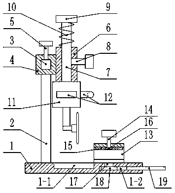
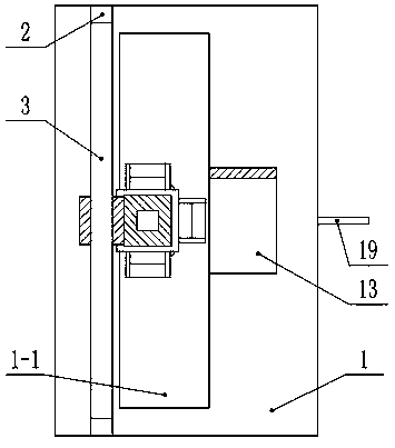

Image

  • Timber cutting device
  • Timber cutting device

Examples


Embodiment Construction

[0013] Below in conjunction with accompanying drawing and specific embodiment the present invention is described in further detail:

[0014] Such as figure 1 with figure 2 As shown, a wood cutting device includes a base 1, two brackets 2 are symmetrically fixed on the upper end of the base 1, a cross bar 3 is fixed between the two brackets 2, and a first sleeve is covered on the cross bar 3 4 and is slidably connected with it, the first sleeve 4 is provided with a first bolt 5 for fastening the cross bar 3, the side end of the first sleeve 4 is fixed with a second sleeve 6, and the second sleeve A vertical rod 7 passes through the barrel 6 and is slidably connected with it. The second sleeve 6 is provided with a second bolt 8 for fastening the vertical rod 7. The upper end of the vertical rod 7 is fixed with a stopper 9. Between the block 9 and the second sleeve 6, a spring 10 is set on the vertical bar 7, the lower end of the vertical bar 7 is fixed with a cutting machine ...


PUM


Abstract

The invention discloses a timber cutting device including a pedestal. Two supports are symmetrically fixed to the upper end of the pedestal. A transversal rod is fixed between the two supports and issleeved with a first sleeve in a sliding connection manner. A first bolt for fastening the transversal rod is arranged on the first sleeve. A second sleeve is fixed to a side end of the first sleeve.A vertical rod is sleeved with the second sleeve in a sliding connection manner. A second bolt for fastening the vertical rod is arranged on the second sleeve. A baffle piece is fixed to the upper endof the vertical rod. A spring sleeving the vertical rod is arranged between the baffle piece and the second sleeve. A cutting machine is fixed to the lower end of the vertical rod. A square groove isformed in the pedestal under the cutting machine. Handles are fixed to the front side, back side and side ends of the cutting machine. A U-shaped board is arranged beside the square groove. A first bolt bar passes through the upper wall of the U-shaped board in a threaded connection manner. A top plate is attached to the lower end of the upper wall of the U-shaped board. The lower end of the first bolt bar in inserted in the top plate and is fixedly provided with a round sheet. The device is convenient to use and can satisfy practical application demands.

Description

technical field [0001] The invention relates to the field of wood product processing, in particular to a wood cutting device. Background technique [0002] Existing wood cutting devices can only cut long strips of wood material at a fixed angle, and cannot adjust the angle of wooden strips or planks, so as to meet actual use requirements. The dust generated during cutting will pollute the environment without effective collection and cleaning. During the use of the cutting machine, it needs to be completely manually lowered or lifted, which delays time. The cutting machine can only cut from top to bottom, and cannot cut horizontally, which cannot meet the cutting of long objects such as planks. Contents of the invention [0003] In order to solve the above existing problems, the present invention provides a wood cutting device. [0004] The present invention is realized through the following technical solutions: [0005] A wood cutting device, comprising a base, two bra...

Claims


Application Information

Patent Timeline
Patent Type & Authority Applications(China)
IPC IPC(8): B27C5/02B27C5/06
CPCB27C5/02B27C5/06
Inventor 周中苏
Owner 江苏树仁木业有限公司
Learn More