
Workbench being convenient to cut timber

A workbench and wood technology, applied in the field of wood processing, can solve the problems of long adjustment time, troublesome structure adjustment, time-consuming and labor-intensive efficiency, etc., to achieve simple and convenient adjustment, improve work efficiency, and ensure cleanliness

Inactive Publication Date: 2019-01-29
江苏树仁木业有限公司
View PDF0 Cites 0 Cited by
  • Summary
  • Abstract
  • Description
  • Claims
  • Application Information

AI Technical Summary

Problems solved by technology

[0002] Wood is a natural raw material, which is processed from wood. Wood processing is relatively simple and convenient, and has the advantages of drying, insulation, and beauty. Therefore, it is often used in daily life. Wood processing is essential in the process of making wood. The most important thing is the cutting process. The wood is cut according to the required width, and it is processed into various types of wood for use. The existing wood cutting workbench controls the cutting width by adjusting the distance between the baffle and the cutting blade. If cutting When repeated cutting with different widths is required, it is necessary to constantly adjust the distance between the baffle and the cutting blade. The usual adjustment structure is very troublesome. Every adjustment needs to observe the baffle and the scale. The adjustment time is long, time-consuming and labor-intensive, and the efficiency is low. Repeated observation The adjustment of the baffle and the scale will inevitably make mistakes and cause waste, so it needs to be improved

Method used


Image

  • Workbench being convenient to cut timber
  • Workbench being convenient to cut timber
  • Workbench being convenient to cut timber

Examples


Embodiment Construction

[0014] Below in conjunction with accompanying drawing and specific embodiment the present invention is described in further detail:

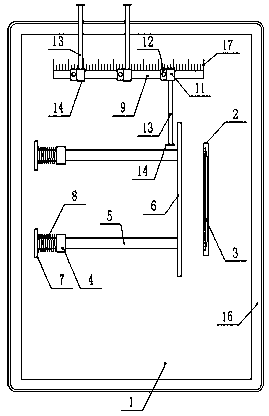
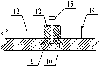
[0015] Such as figure 1 , figure 2 , image 3 As shown, a workbench that is convenient for cutting wood includes a workbench 1, a through groove 2 is provided on the workbench 1, and a cutting piece 3 driven by a motor is arranged in the through groove 2, and it is characterized in that: the workbench 1 Two mutually parallel sleeves 4 are fixed on the top, and a cross bar 5 slidingly connected with it is inserted in the sleeve 4, and a baffle plate 6 parallel to the cutting piece 3 is fixed on one end of the cross bar 5, and the cross bar 5 The other end of the baffle plate 7 is fixed, and a spring 8 is set on the outer wall of the cross bar 5 between the baffle plate 7 and the sleeve 4. The workbench 1 is horizontally provided with a trapezoidal groove 9 parallel to the cross bar 5, and the trapezoidal The groove 9 is provided with a plural...


PUM


Abstract

The invention discloses a workbench being convenient to cut timber, which includes a work table. A penetrating groove is formed in the work table and a cutting blade driven by a motor is arranged in the penetrating groove. The workbench is characterized in that two sleeves are fixed to the top of the work table in parallel with each other, wherein transversal rods are inserted, in a sliding connection manner, into the sleeves; a baffle in parallel with the cutting blade is fixed to one end of each transversal rod; a baffle plate is fixed to the other end of each transversal rod; springs, sleeving the outer wall of the transversal rods, are arranged between the baffle plates and the sleeves; a trapezoid groove, in parallel with the transversal rods, is transversally formed in the work table, wherein a trapezoid block is in sliding connection with interior of the trapezoid groove; a cylinder is fixed to the upper end of the trapezoid block; a fixing block is fixed to the side end of thecylinder; a position limiting rod is vertically inserted in the fixing block in a threaded connection manner. According to the workbench, common timber cutting widths can be preset, so that the workbench is convenient to adjust and is easy and convenient to use, can increase work efficiency of cutting the timber and reduce possibility of error in adjustment. By a collection groove, sawdust can becollected, so that the workbench is kept clean, thus avoiding influence on cutting and being convenient to clean.

Description

technical field [0001] The invention relates to the field of wood processing, in particular to a workbench for cutting wood. Background technique [0002] Wood is a natural raw material, which is processed from wood. Wood processing is relatively simple and convenient, and has the advantages of drying, insulation, and beauty. Therefore, it is often used in daily life. Wood processing is essential in the process of making wood. The most important thing is the cutting process. The wood is cut according to the required width, and it is processed into various types of wood for use. The existing wood cutting workbench controls the cutting width by adjusting the distance between the baffle and the cutting blade. If cutting When repeated cutting with different widths is required, it is necessary to constantly adjust the distance between the baffle and the cutting blade. The usual adjustment structure is very troublesome. Every adjustment needs to observe the baffle and the scale. T...

Claims


Application Information

Patent Timeline
Patent Type & Authority Applications(China)
IPC IPC(8): B27C5/02B27G3/00
CPCB27C5/02B27G3/00
Inventor 周中苏
Owner 江苏树仁木业有限公司
Learn More