
Vertical H-shaped steel four-face rust removal device

A H-shaped steel, vertical technology, applied in the direction of grinding machines, grinding/polishing equipment, manufacturing tools, etc., can solve the problems of construction danger, time-consuming and labor-intensive, low efficiency, etc., to reduce labor intensity, improve work efficiency, and facilitate operation Effect

Inactive Publication Date: 2019-01-29
LAIWU VOCATIONAL & TECHNICAL COLLEGE
View PDF0 Cites 2 Cited by
  • Summary
  • Abstract
  • Description
  • Claims
  • Application Information

AI Technical Summary

Problems solved by technology

At present, the derusting method for the eight sides of the H-beam is mainly to use mechanical equipment to derust the H-beam that has not been installed. The rolling mill generally uses shot blasting for the H-beam that leaves the factory. However, after the H-beam is built into a workshop, due to The H-shaped steel stands on the ground, and can only rely on manual climbing and manual derusting with wire brushes
Its disadvantages are: because the operator needs to stand at a high place to derust the upper end of the H-beam, the construction is more dangerous, and at the same time, the dust generated during the derusting process with the wire brush will also affect the health of the operator , and the labor intensity of manual rust removal is high, time-consuming and laborious, and the efficiency is low

Method used


Image

  • Vertical H-shaped steel four-face rust removal device
  • Vertical H-shaped steel four-face rust removal device
  • Vertical H-shaped steel four-face rust removal device

Examples


Embodiment Construction

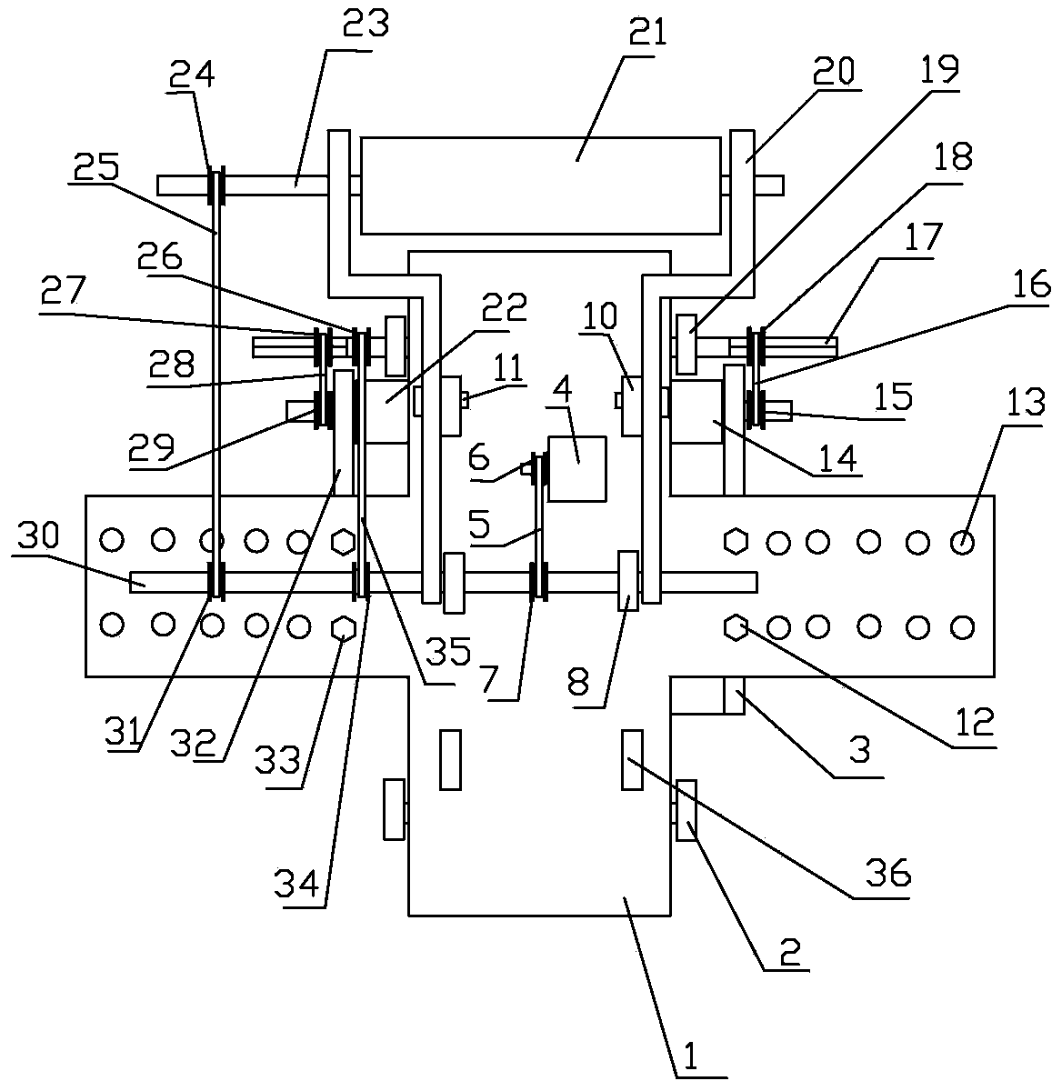
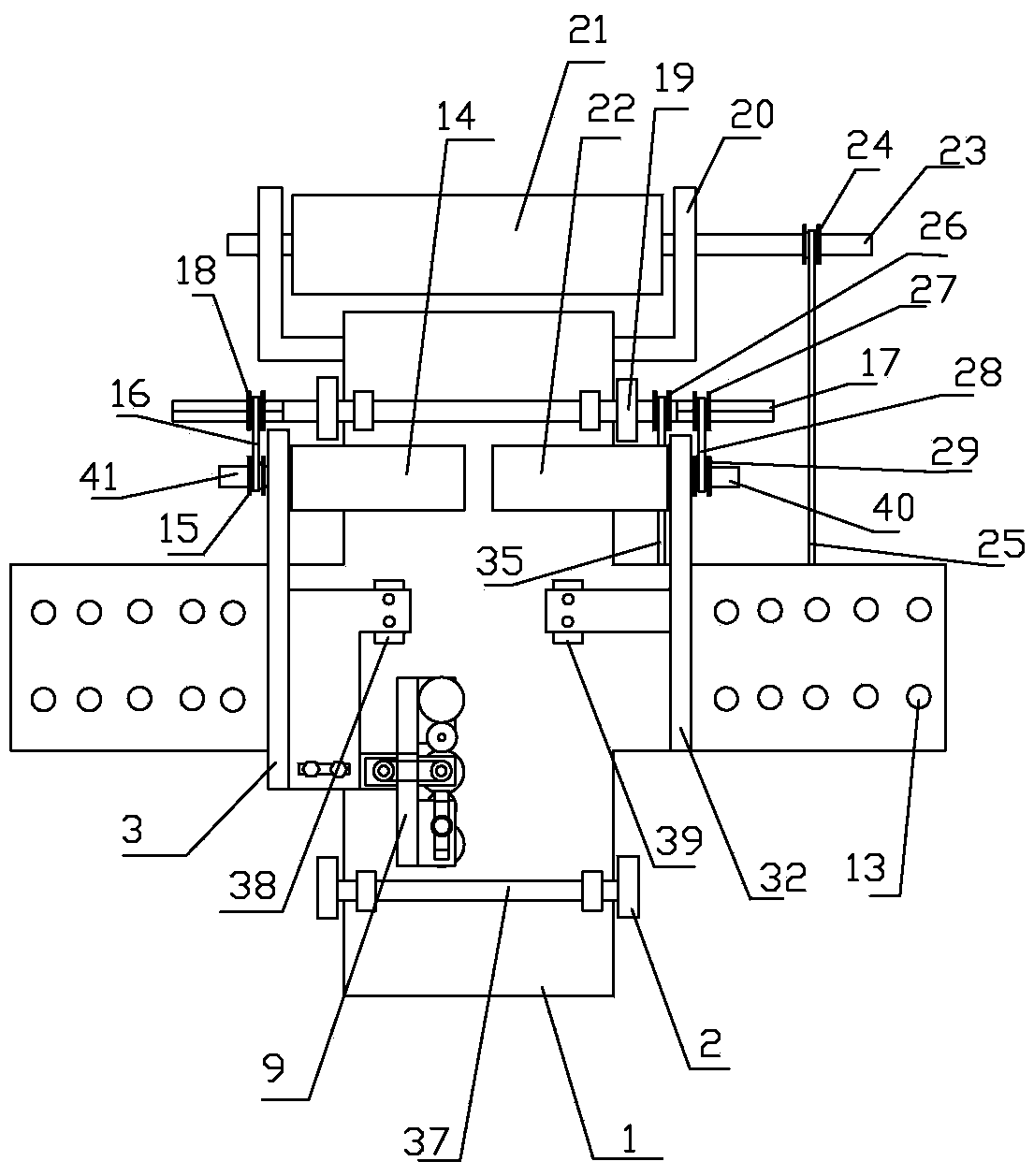
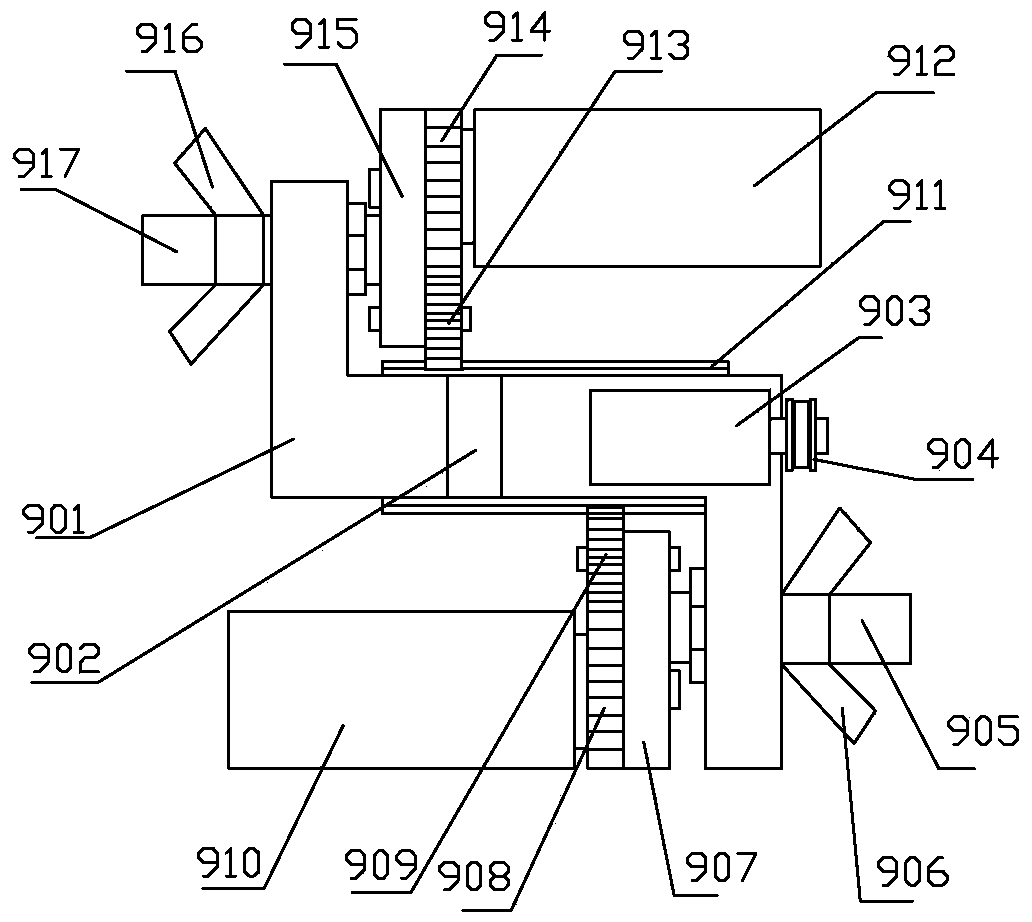
[0020] refer to figure 1 , figure 2 , image 3 , Figure 4 , Figure 5Make the present invention, this vertical H-beam four sides derusting device, comprises vehicle frame 1, No. 3 turning bar 17, front wheel 19, No. 4 turning bar 37, trailing wheel 2, motor and brush roller, is fixedly installed on the vehicle frame 1 There is a No. 1 motor 4, and the No. 1 motor 4 is connected with the PLC controller through wires, and the forward rotation, reverse rotation and rotating speed of the No. 1 motor 4 are controlled by the PLC controller. The front bottom plate of the vehicle frame 1 is provided with a No. 3 rotating rod 17, Two front wheels 19 are fixedly arranged on the No. 3 rotating rod 17, and the rear portion base plate of vehicle frame 1 is provided with No. 4 rotating rod 37 parallel with No. 3 rotating rod 17, and the two ends of No. 4 rotating rod 37 are fixedly installed respectively. There are rear wheels 2, two front wheels 19 and two rear wheels 2 are placed on...


PUM


Abstract

The invention discloses a vertical H-shaped steel four-face rust removal device. The vertical H-shaped steel four-face rust removal device comprises a frame, a third rotary rod, a front wheel, a fourth rotary rod, a rear wheel, motors and brush rollers. The vertical H-shaped steel four-face rust removal device is characterized in that a first rotary rod is arranged in the middle of the frame, andthe first motor and the first rotary rod are in transmission; a second rotary rod is arranged at the front end of a clamping rod, the front brush roller is arranged on the second rotary rod, and the first rotary rod and the second rotary rod are in transmission; the first rotary rod and the third rotary rod are in transmission; a left rotary shaft is arranged at the front end of a left fixing plate of the frame, the left brush roller is arranged on the left rotary shaft, and the left rotary shaft and the third rotary rod are in transmission; a right rotary shaft is arranged at the front end ofa right fixing plate of the frame, the right brush roller is arranged on the right rotary shaft, and the right rotary shaft and the third rotary rod are in transmission; a left clamping wheel is arranged in the middle of the left fixing plate, and a right clamping wheel is arranged in the middle of the right fixing plate; and a web roll-brushing device is fixedly arranged on the rear portion of the right fixing plate. Standing H-shaped steel can be rapidly subjected to rust removal, the four faces of the H-shaped steel can be cleaned at a time, and therefore time and labor are saved.

Description

technical field [0001] The present invention relates to an improvement of an H-shaped steel derusting device, specifically a vertical H-shaped steel derusting device on four sides, which is suitable for simultaneous derusting on four sides of an H-shaped steel standing on the ground in a built workshop used when. Background technique [0002] H-shaped steel is a high-efficiency profile, named for its section that is the same as the English letter "H". Since all parts of H-shaped steel are arranged at right angles, H-shaped steel has the advantages of strong bending resistance, simple construction, cost saving and light structure weight. H-shaped steel is mainly used in various civil and industrial building structures, especially industrial plants. . The H-shaped steel is composed of two flange plates and a web, each flange plate has a front plate surface and two back plate surfaces, and the web plate has two left and right web surfaces. In this way, the H-shaped steel has ...

Claims


Application Information

Patent Timeline
Patent Type & Authority Applications(China)
IPC IPC(8): B24B27/033B24B41/06B24B41/02
CPCB24B27/033B24B41/02B24B41/06
Inventor 孙贵斌董志颖李坤淑孙召瑞陈军
Owner LAIWU VOCATIONAL & TECHNICAL COLLEGE
Learn More