
Cutting and milling dual-purpose permanent magnet servo motor

A permanent magnet servo motor, a dual-purpose technology, applied in the direction of electrical components, electromechanical devices, electric components, etc., can solve the problems of affecting the service life of processing equipment, the accuracy is greatly affected by the quality, and the milling dimensional accuracy is insufficient, so as to save installation Time, structure design is simple and reasonable, and the effect of high processing precision

Pending Publication Date: 2019-01-25
浙江斯耐特动力股份有限公司
View PDF0 Cites 0 Cited by
  • Summary
  • Abstract
  • Description
  • Claims
  • Application Information

AI Technical Summary

Problems solved by technology

[0003] At present, in the existing marble processing equipment on the market, the cutting wheel and the milling cutter are fixed on the processing equipment body and cannot be moved. It is heavy and consumes a lot of energy for frequent movement. Moreover, the accuracy of the movement position is greatly affected by the quality, and it is prone to insufficient dimensional accuracy of cutting and milling, which wastes materials and increases the cost of investment. It is inevitable during cutting and grinding. Marble powder will be raised, if the sealing of cutting equipment is not good, it will greatly affect the service life of processing equipment

Method used


Image

  • Cutting and milling dual-purpose permanent magnet servo motor
  • Cutting and milling dual-purpose permanent magnet servo motor
  • Cutting and milling dual-purpose permanent magnet servo motor

Examples


Embodiment Construction

[0031] The present invention will be further described below in conjunction with the accompanying drawings and specific embodiments (embodiments). The specific embodiments described here are only used to explain the present invention, but not as a basis for limiting the present invention.

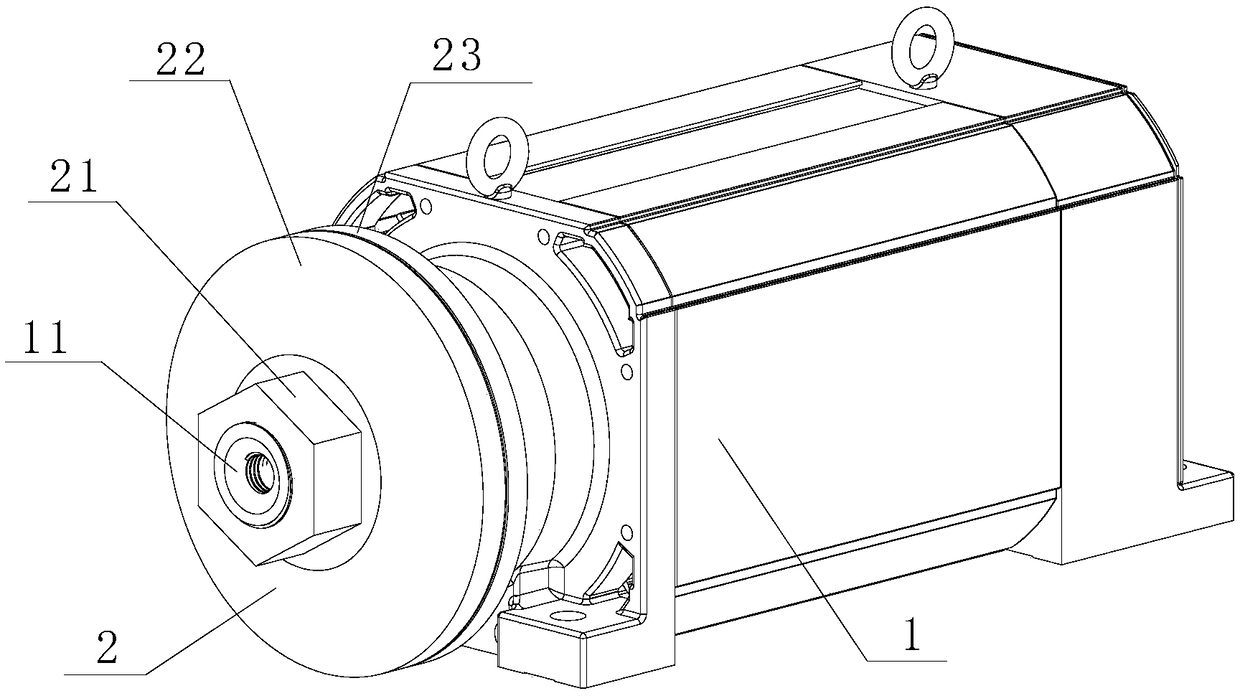
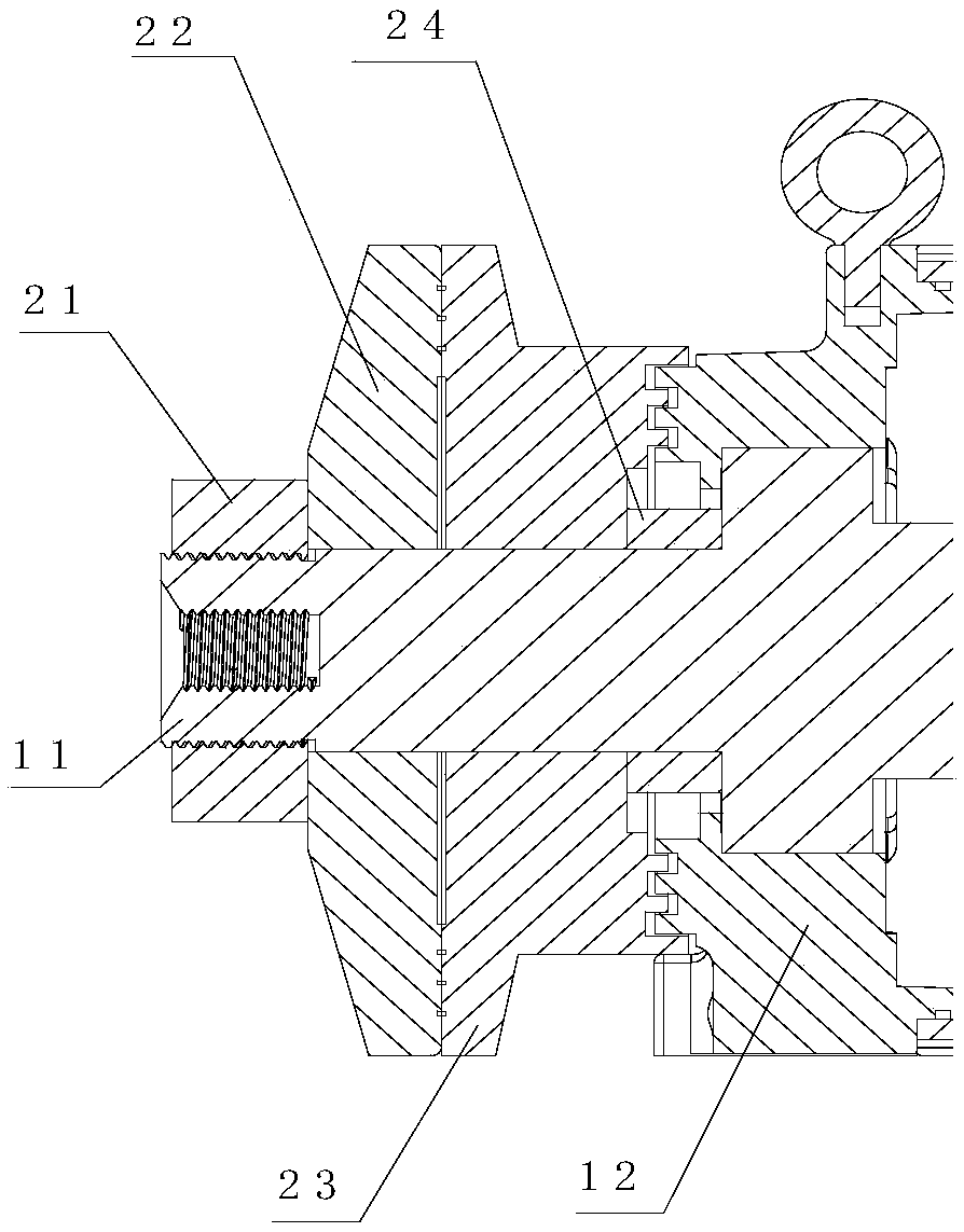
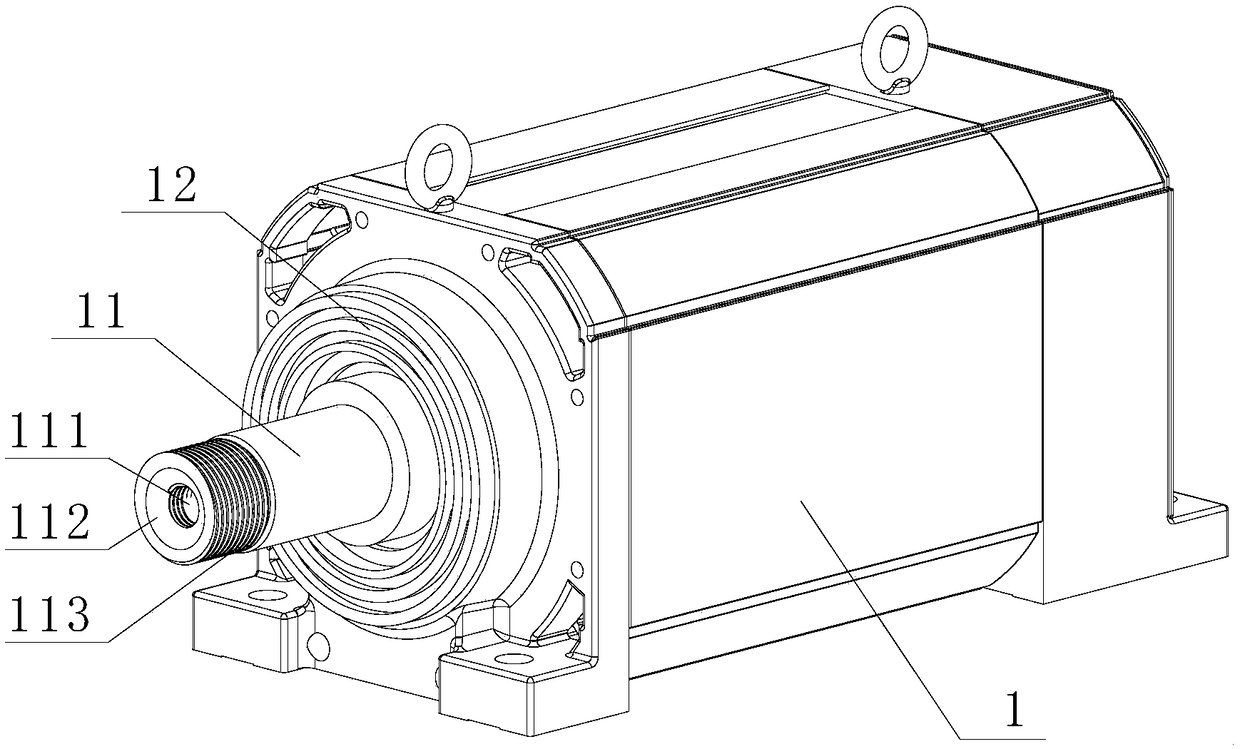
[0032] see Figure 1-13 , the dual-purpose permanent magnet servo motor for cutting and milling of the present invention includes a motor body 1 and a cutting blade clamping device 2; surface 112 and milling cutter mounting surface 111, the outer periphery of the front end of the motor shaft 11 has a locking device mounting surface 113; The disc 23 , the front clamping disc 22 of the cutting blade and the locking member 21 of the clamping device;

[0033] As a specific embodiment, the mounting surface 113 of the locking device is screw-fitted with the locking member 21 of the clamping device. It is convenient to disassemble and adjust the clamping force of the cutting blade clamping devic...


PUM


Abstract

The invention discloses a cutting and milling dual-purpose permanent magnet servo motor, which comprises a motor body and a cutting blade clamping device. The middle part of the motor shaft front endof the motor body is sequentially provided with a milling cutter limit surface and a milling cutter mounting surface adapted to the milling cutter, and the outer periphery of the motor shaft front endis provided with a locking device mounting surface; The cutting blade clamping device comprises a positioning sleeve sequentially sleeved on a motor shaft, a cutting blade rear clamping disk, a cutting blade front clamping disk and a clamping device locking member; the cutting blade clamping device comprises a positioning sleeve sequentially sleeved on a motor shaft, a cutting blade rear clampingdisk, a cutting blade front clamping disk and a clamping device locking member. A loc piece of that clamping device is match with the mounting surface of the locking device for pressing the cutting blade front chuck. The invention has the advantages of simple and reasonable structure design, diverse functions, and dual-purpose of milling and cutting. The utility model is suitable for the machining method of the moving fuselage and the fixed workpiece, which has the characteristics of low moving energy consumption and high machining precision, and is more suitable for various milling and cutting working conditions; The cutting insert and the milling cutter are convenient to be installed and disassembled, the clamping and disassembling steps are reduced, the installation time is saved, andthe operability is good.

Description

technical field [0001] The invention relates to the technical field of marble processing, in particular to a dual-purpose permanent magnet servo motor for cutting and milling. Background technique [0002] Natural marble has the characteristics of irregular shape and high hardness. In the process of marble processing, cutting is the first process, and milling the surface is the second process. Therefore, it is usually necessary to replace cutting blades and milling cutters frequently during processing. . [0003] At present, in the existing marble processing equipment on the market, the cutting wheel and the milling cutter are fixed on the processing equipment body and cannot be moved. It is heavy and consumes a lot of energy for frequent movement. Moreover, the accuracy of the movement position is greatly affected by the quality, and it is prone to insufficient dimensional accuracy of cutting and milling, which wastes materials and increases the cost of investment. It is i...

Claims


Application Information

Patent Timeline
IPC IPC(8): H02K7/14H02K5/04H02K5/10B28D1/22B28D1/18
CPCH02K5/04H02K5/10H02K7/14B28D1/186B28D1/22
Inventor 黄海成鲁萍萍舒仲撑涂春节王成
Owner 浙江斯耐特动力股份有限公司
Learn More