Rotor and depolymerization device
A rotor and shaft technology, applied in the field of rotors and depolymerization devices, can solve the problems of high production cost, high power of peripheral drive devices, and large overall quality, and achieve the effects of reducing production costs, round and beautiful appearance, and reducing overall quality
- Summary
- Abstract
- Description
- Claims
- Application Information
AI Technical Summary
Problems solved by technology
Method used
Image

Examples
Embodiment 1
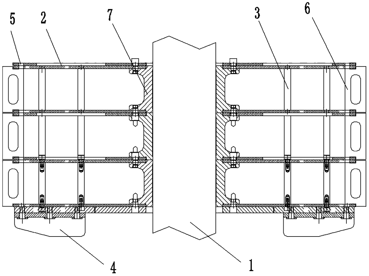
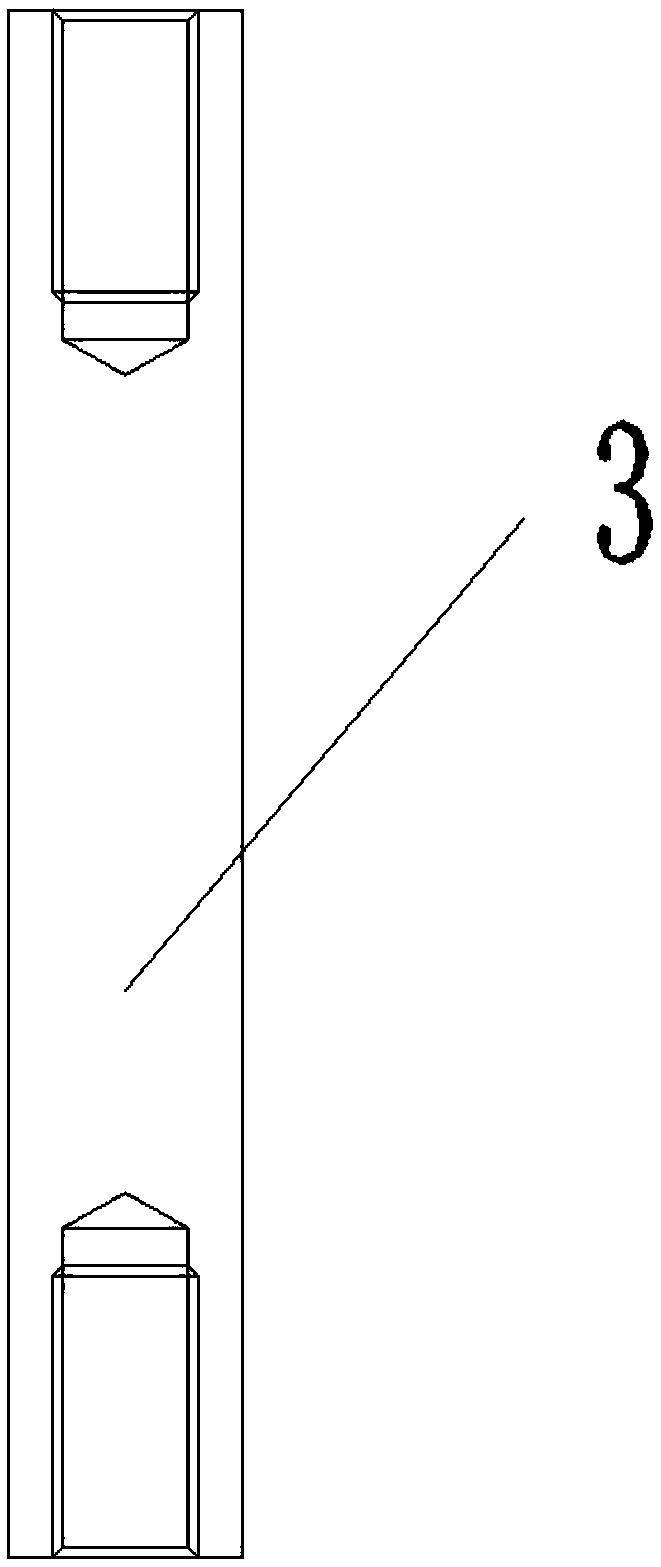
[0026] see Figure 1 to Figure 3 , Figure 1 to Figure 3 A specific embodiment of a rotor of the present invention is provided, wherein, figure 1 It is a front view of the rotor disclosed in Embodiment 1 of the present invention; figure 2 It is a top view of the rotor disclosed in Embodiment 1 of the present invention, image 3 It is a schematic structural diagram of the clamping rod disclosed in Embodiment 1 of the present invention.
[0027] like Figure 1 to Figure 3 As shown, the rotor provided in this embodiment includes a rotating shaft 1 , a disc 2 , a clamping rod 3 , a dispersion piece 4 , a slot 5 and a decoration piece 6 .
[0028] In this embodiment, the rotating shaft 1 is generally connected with the external power drive equipment, and the rotating shaft 1 is used for power transmission.
[0029] Discs 2 are arranged layer by layer on the outer periphery of the rotating shaft 1 at intervals, and clamping bars 3 are provided between the discs 2 in adjacent l...
Embodiment 2
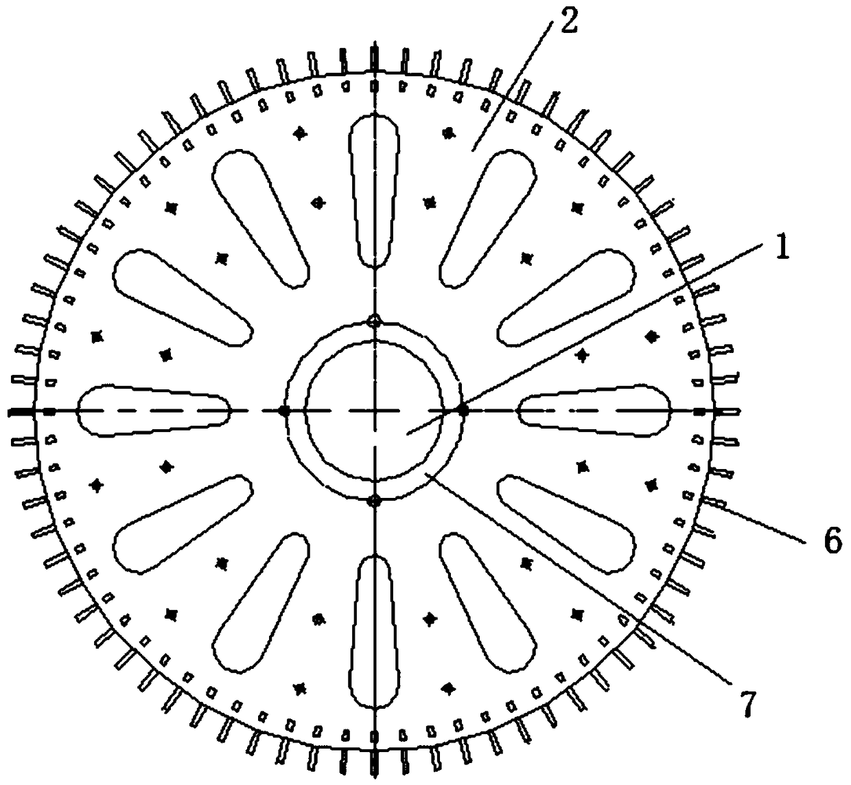
[0038] see Figure 4 , Figure 4 A specific embodiment of a disc of the present invention is provided, wherein, Figure 4 It is a top view of the disc disclosed in Embodiment 2 of the present invention.
[0039] like Figure 4 As shown, the disc 2 provided in this embodiment includes a disc body 201, and the center of the disc body 201 is provided with a shaft hole 202 for the installation of the rotating shaft 1, and the outer periphery of the shaft hole 202 is annularly spaced. Lightening holes 203 are equidistantly arranged, and threaded holes 204 matched with the clamp rod 3 are provided on the end surface of the disc body 201 .
[0040] Specifically, the diameter and thickness of the disc body 201 are selected and designed according to actual needs. The diameter of the shaft hole 202 is also designed to match the diameter of the external shaft 1 .
[0041] In this embodiment, weight-reducing holes 203 are evenly dug on the disk body 201, thereby greatly reducing the ...
Embodiment 3
[0045] see Figure 5 to Figure 7 , Figure 5 to Figure 7 A specific embodiment of a dispersible tablet of the present invention is provided, wherein, Figure 5 It is the front view of the dispersible tablet disclosed in Embodiment 3 of the present invention; Image 6 It is a top view of the dispersible tablet disclosed in Embodiment 3 of the present invention; Figure 7 It is the left view of the dispersible tablet disclosed in Example 3 of the present invention.
[0046] like Figure 5 to Figure 7 As shown, preferably, the dispersing sheet 4 includes horizontally arranged horizontal plates 401 and vertically arranged vertical plates 402, the horizontal plates 401 are detachably connected to the disc 2, and the vertical plates 402 One side intersects with the horizontal plate 401 and the other side is provided with an oblique guide surface 403 . Preferably, the flow guiding direction of the oblique flow guiding surface 403 is outward along the center of the circle.
[00...
PUM
 Abstract
Description
Claims
Application Information
 - R&D
- Intellectual Property
- Life Sciences
- Materials
- Tech Scout
- Unparalleled Data Quality
- Higher Quality Content
- 60% Fewer Hallucinations
Browse by: Latest US Patents, China's latest patents, Technical Efficacy Thesaurus, Application Domain, Technology Topic, Popular Technical Reports.
© 2025 PatSnap. All rights reserved.Legal|Privacy policy|Modern Slavery Act Transparency Statement|Sitemap|About US| Contact US: help@patsnap.com