
Door sealing structure and construction method used in shield launching and receiving construction

A construction method and technology in construction, applied in basic structure engineering, earthwork drilling, construction, etc., can solve the problems of high construction technology requirements, worn cutter heads, long construction period, etc., to improve shield efficiency and reduce cutter The effect of head wear and shortened construction period

Active Publication Date: 2021-05-04
SOUTHWEAT UNIV OF SCI & TECH
View PDF5 Cites 0 Cited by
  • Summary
  • Abstract
  • Description
  • Claims
  • Application Information

AI Technical Summary

Problems solved by technology

[0007] When the foundation pit is excavated, the fiber reinforcement cage is hoisted. Under the action of self-weight and unfavorable impact of on-site construction, the fiber reinforcement is seriously brittle. It is necessary to use segmented and framing methods to hoist the reinforcement cage. long
[0008] At the same time, there will still be a small amount of fiber tendons winding around the cutter head and pulling the surrounding concrete, which will wear the cutter head and cause the surrounding concrete to crack

Method used


Image

  • Door sealing structure and construction method used in shield launching and receiving construction
  • Door sealing structure and construction method used in shield launching and receiving construction
  • Door sealing structure and construction method used in shield launching and receiving construction

Examples


Embodiment Construction

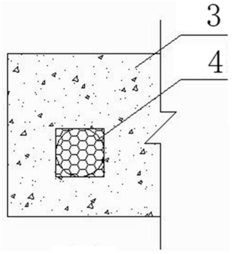
[0027] figure 2 It shows a door-sealing structure used in shield launching and receiving construction, which includes an underground continuous wall: a steel cage embedded in concrete as a skeleton, and the bottom of the shield circular penetration area corresponding to the steel cage 1 is transversely A bottom steel plate 2a is welded, and two side steel plates 2b and 2c of the same size as the bottom steel plate are respectively vertically welded on the left and right sides of the bottom steel plate to form a square upper opening steel formwork, and the corresponding vertical steel bars on the reinforcement cage 1 and The upper and lower surfaces of the bottom steel plate are welded together, and multiple steel bars are welded horizontally between the two side steel plates 2b and 2c; the length of the above bottom steel plate 2a is the diameter of the tunnel plus 1m, the thickness is 2cm to 5cm, and the width is equal to the thickness of the underground diaphragm wall Sulfu...


PUM


Abstract

A door-sealing structure and its construction method used in shield launching and receiving construction. The underground diaphragm wall is composed of a steel cage embedded in concrete as a skeleton. Steel plate, two side steel plates of the same size as the bottom steel plate are vertically welded on the left and right sides of the bottom steel plate to form a square upper opening steel formwork, and the corresponding vertical steel bars on the reinforcement cage are welded to the upper and lower surfaces of the bottom steel plate. A number of steel bars are welded horizontally between the two side steel plates; the length of the above-mentioned bottom steel plate is the diameter of the tunnel plus 1m, the thickness is 2cm to 5cm, and the width is equal to the thickness of the underground diaphragm wall; sulfur concrete is poured in the upper opening steel formwork, and the upper opening steel The underground continuous wall other than the formwork is poured with ordinary concrete; the invention solves the problems of traditional shield tunneling methods such as winding the cutter head, head-to-head contact between the cutter head and the steel bar, and pulling the surrounding concrete, and has the characteristics of reducing the loss of the shield machine cutter head and improving the efficiency of the shield tunneling machine .

Description

technical field [0001] The invention relates to a supporting structure in the construction of a shield machine, in particular to a concrete door sealing structure and a construction method used together in the starting and receiving construction of the shield machine. Background technique [0002] The underground diaphragm wall adopts a reinforced concrete structure, the steel cage is hoisted integrally or step by step, the concrete is cast in place as a whole, and the shield machine penetrates the underground diaphragm wall. [0003] During the tunnel construction process, the shield machine will penetrate the underground continuous wall during the starting and receiving process, and the cutter head of the shield machine will produce a lot of wear and tear. The steel bars will wrap around the cutter head, and at the same time, the surrounding steel bars will tear the surrounding concrete, causing a series of problems such as cracking of the surrounding concrete and difficul...

Claims


Application Information

Patent Timeline
Patent Type & Authority Patents(China)
IPC IPC(8): E21D9/06E02D5/18
CPCE02D5/187E21D9/06
Inventor 孔超朱晓璐梁远刘高洁刘雪松顾颖任松波
Owner SOUTHWEAT UNIV OF SCI & TECH
Learn More