
A three-dimensional modeling method of diffractive optical element based on matrix transformation

A technology for diffractive optical elements and three-dimensional modeling, which is applied in the field of three-dimensional modeling of diffractive optical elements based on matrix transformation, and can solve the problems that the surface of diffractive optical elements is difficult to represent, the processing method is cumbersome, and the workload of analysis and calculation is large.

Active Publication Date: 2019-01-22
TIANJIN UNIV
View PDF2 Cites 2 Cited by
  • Summary
  • Abstract
  • Description
  • Claims
  • Application Information

AI Technical Summary

Problems solved by technology

[0006] First, due to the large number of surface structure units, the operation method of traditional 3D modeling software to process units one by one is very cumbersome and uneconomical, and the workload of analysis and calculation is huge
Second, since each sampling unit of the non-periodic diffractive optical element is independent of each other in the phase calculation process, it is difficult to express the surface of the complex surface diffractive optical element with a periodic function or a general analytical function
Therefore, it is very difficult to establish a high-precision 3D model that can accurately reflect surface features

Method used


Image

  • A three-dimensional modeling method of diffractive optical element based on matrix transformation
  • A three-dimensional modeling method of diffractive optical element based on matrix transformation
  • A three-dimensional modeling method of diffractive optical element based on matrix transformation

Examples


Embodiment 1

[0029] It is designed to make the modeling process of aperiodic continuous relief diffractive optical elements fast, accurate and efficient. Broaden the way for micro-nano processing of diffractive optical elements, including traditional processing methods, such as diamond cutting, and other processing methods, such as micro-nano 3D printing.

[0030] This implementation example proposes a modeling method for diffractive optical elements based on matrix transformation.

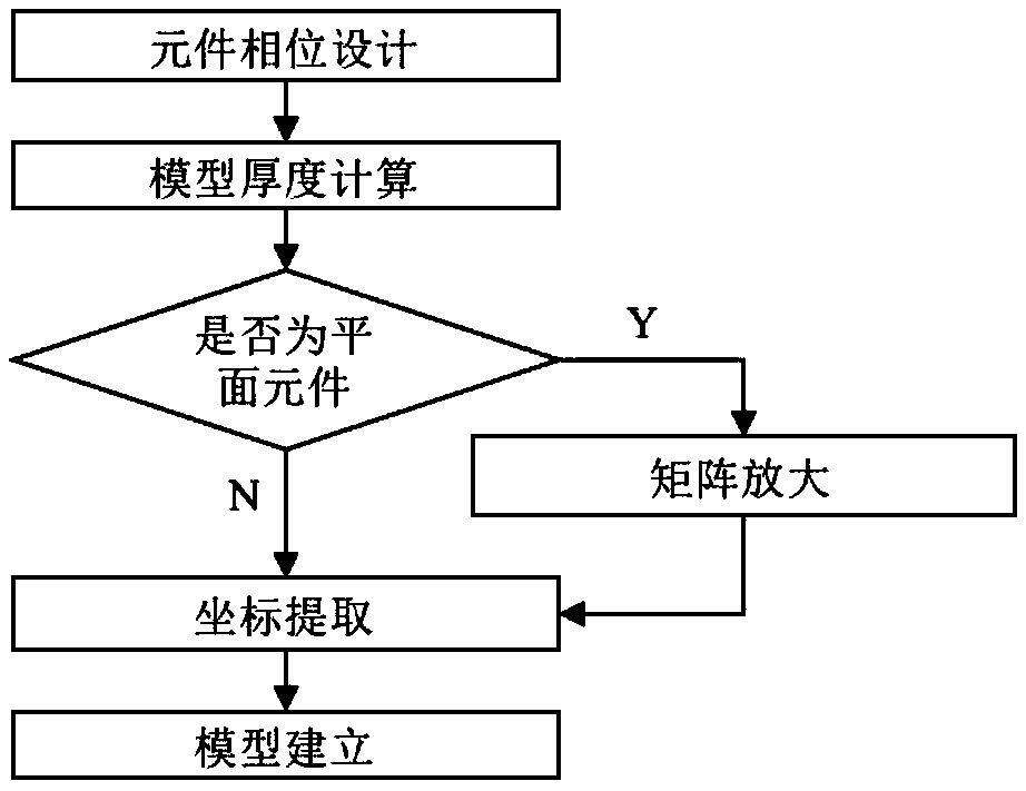
[0031] The phase matrix is ​​designed through the optimization algorithm implemented by MATLAB, the corresponding relationship between the point cloud and the phase matrix data is established, and the point cloud file that can be directly read by Pro / E is generated, and the high-precision model is generated from the obtained point cloud file using the method of reverse engineering.

[0032] This method mainly adopts the idea of ​​combining data conversion and reverse engineering, and consists of four main modu...


PUM


Abstract

The invention relates to a three-dimensional modeling method of a diffractive optical element based on matrix conversion, comprising a phase design step, a model thickness calculation step, a matrix amplification step, a point cloud extraction step and a model generation step. The invention realizes the rapid three-dimensional modeling of the complex surface optical element through the mode of matrix conversion and the idea of reverse engineering. Compared with the traditional methods, the proposed method has obvious advantages in modeling aperiodic continuous relief diffractive optical elements, and can preserve the surface details to the maximum extent, thus establishing a high-precision diffractive optical element model.

Description

technical field [0001] The invention belongs to the technical fields of phase calculation, point cloud conversion, three-dimensional model design and the like of optical elements, in particular a three-dimensional modeling method for diffractive optical elements based on matrix transformation. Background technique [0002] Establishing a three-dimensional model of an optical element is an important way to characterize and process the optical element. There are two ways to establish a three-dimensional model of a traditional circularly symmetric optical element. One is based on the geometric parameters or phase function obtained by ZEMAX design, using MATLAB The software uses the MZDDE toolbox to realize the communication between MATLAB software and ZEMAX software, and then calls the process parameters calculated by the ZEMAX software to draw the designed surface; the other is to use the external extension function of the ZEMAX software to write the parameters into DOEplot Pr...

Claims


Application Information

Patent Timeline
Patent Type & Authority Applications(China)
IPC IPC(8): G06F17/50G06T17/00
CPCG06T17/00G06F30/20
Inventor 赵彦博袁宇焜顾春阳房丰洲
Owner TIANJIN UNIV
Learn More