
Control method of monitoring ball machine

A control method and ball camera technology, applied in image analysis, instruments, closed-circuit television systems, etc., can solve the problems of long time-consuming positioning scanning and low degree of automation, and achieve fast image capture speed, expanded field of view, and integrity assurance Effect

Inactive Publication Date: 2015-05-20
HUAZHONG UNIV OF SCI & TECH
View PDF5 Cites 24 Cited by
  • Summary
  • Abstract
  • Description
  • Claims
  • Application Information

AI Technical Summary

Problems solved by technology

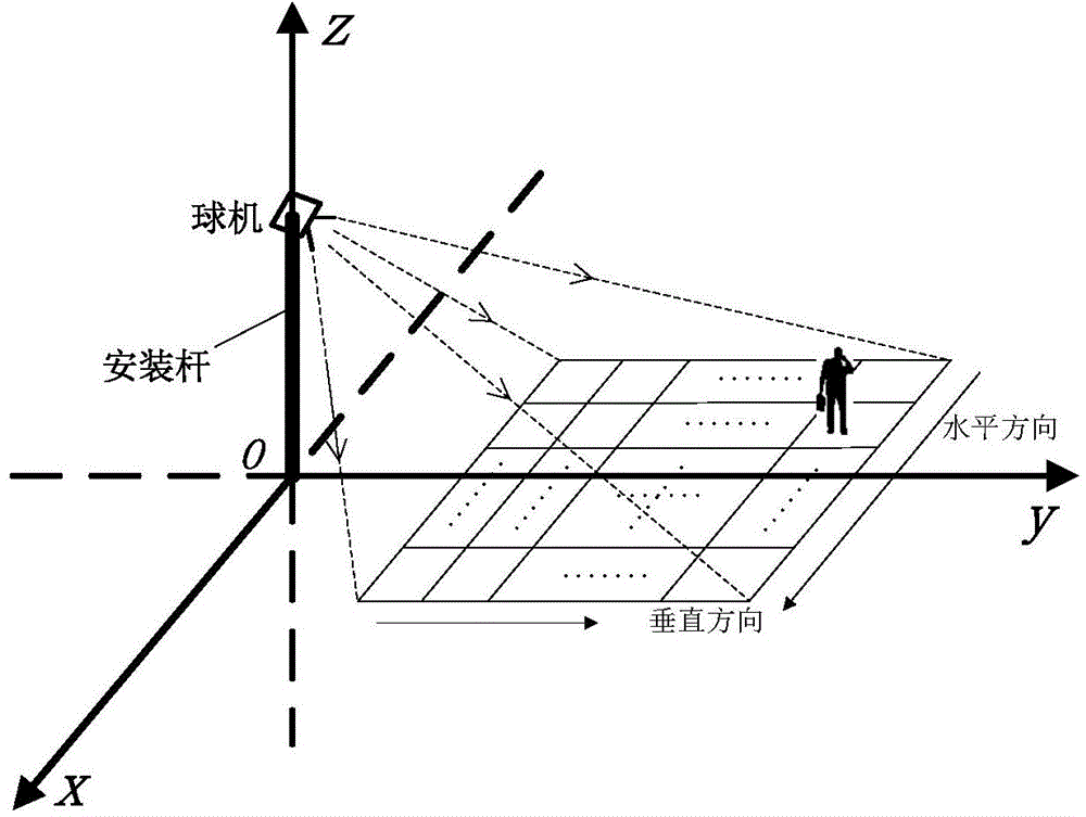
[0006] Aiming at the above defects or improvement needs of the prior art, the object of the present invention is to provide a control method for a speed dome camera, in which, by improving its partition method, focal length calculation method, preset position setting method, etc., it is different from the existing Compared with the technology, it can effectively solve the problems of low automation of dome camera control and long time-consuming positioning and scanning in traditional video surveillance, and the control method of the dome camera can not only ensure the scope of the monitoring field of view, but also accurately monitor the details in the field of view. Zoom in to ensure the clarity of the image and the monitoring effect, especially for moving objects, which can further ensure the monitoring quality

Method used


Image

  • Control method of monitoring ball machine
  • Control method of monitoring ball machine
  • Control method of monitoring ball machine

Examples


Embodiment 1

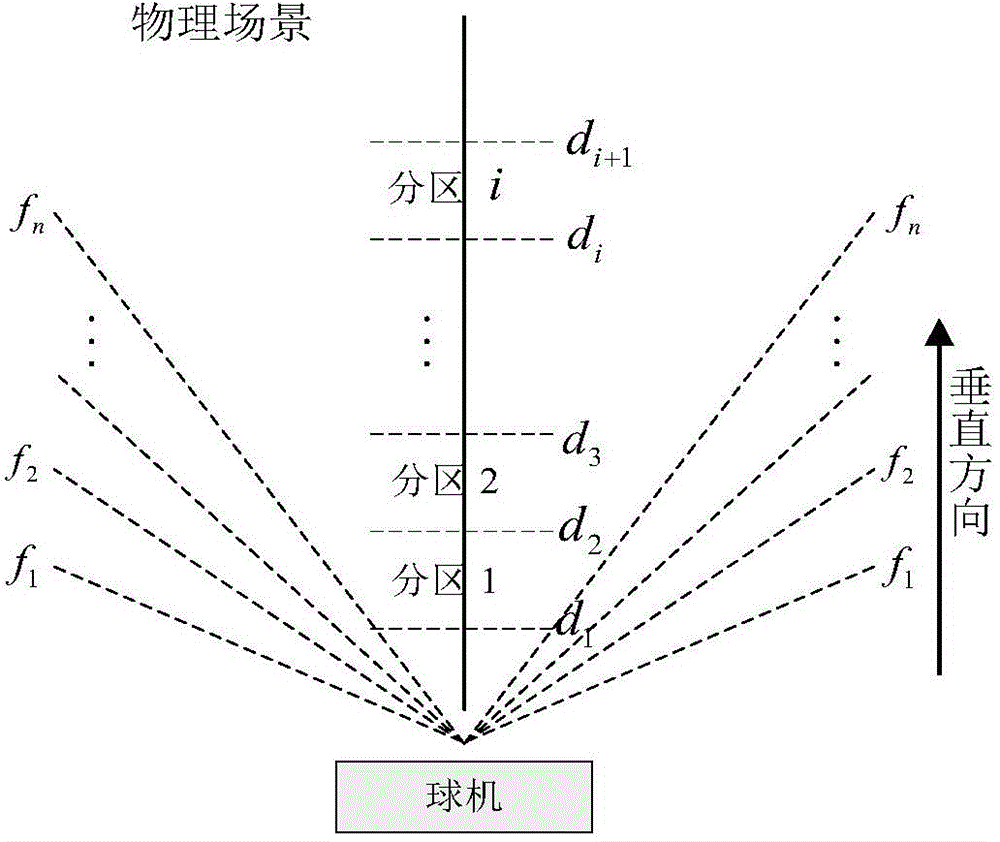
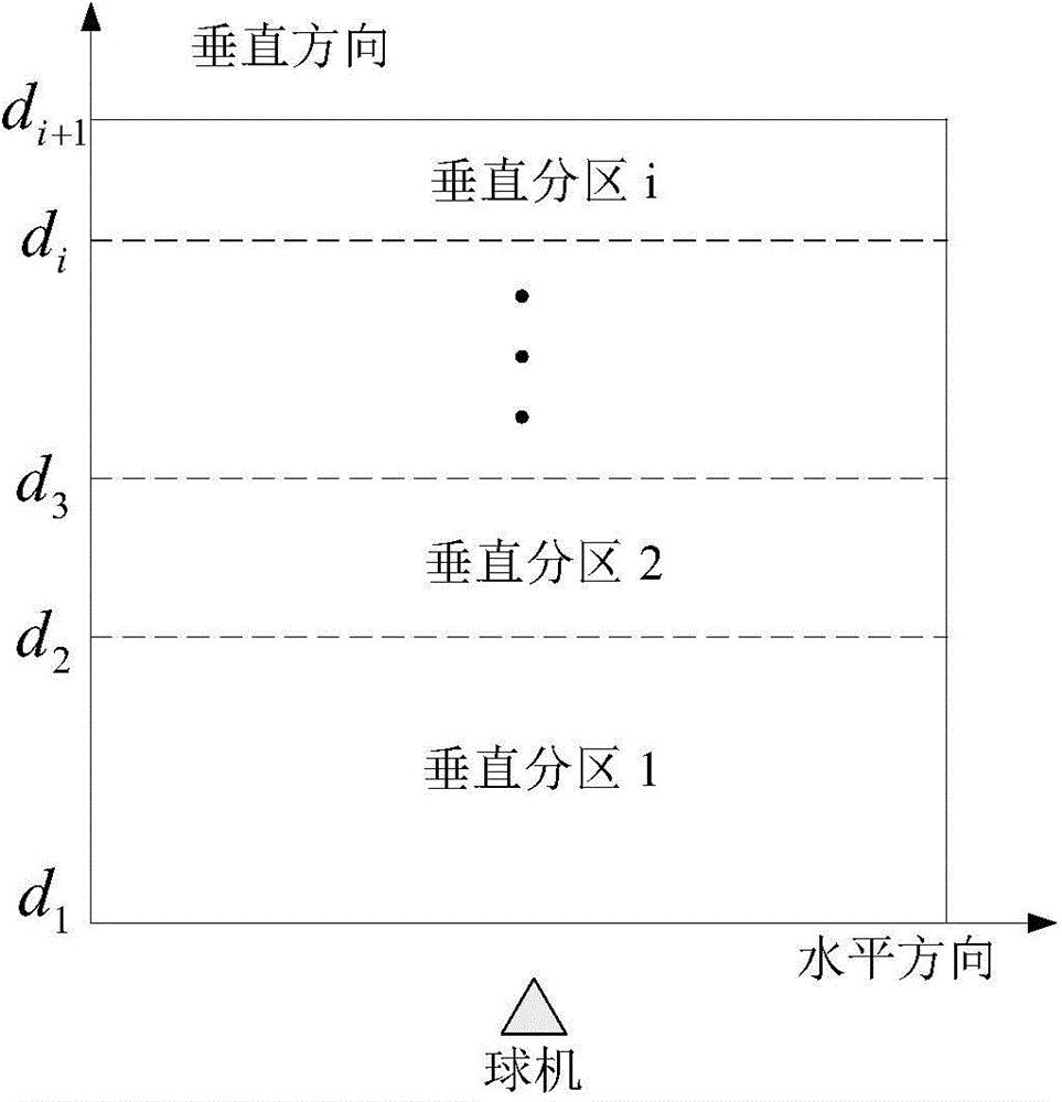
[0037] The present invention can be divided into two aspects: configuration process and real-time monitoring process. The configuration process refers to dividing the monitoring scene into horizontal and vertical partitions according to the speed dome parameters, scene information and target resolution requirements before implementing monitoring, then determining the shooting focal length of each partition and setting the preset position, and saving the dome camera orientation information and magnification information. The real-time monitoring process means that the monitoring system performs video analysis on the video frames captured by the camera during work, detects the position of the target and maps it to a specific preset position, and finally the system sends instructions to the dome camera to quickly reach the designated preset position to obtain The high-resolution image of the target, so as to achieve the purpose of identifying the details of the target.

[0038] ...


PUM


Abstract

The invention discloses a control method of a monitoring ball machine. The method comprises the following steps of (1) vertically and horizontally dividing a to-be-monitored space into a plurality of small partitions, and setting a shooting focal distance for each small partition; (2) setting corresponding preset positions for a central point position and an edge point position of each small partition, and storing horizontal position information, vertical position information and shooting focal distance information of the ball machine; (3) reading a video frame, and performing target detection on the video frame; (4) according to direction information of a detected target in a monitoring scene, mapping the target to the corresponding preset position; (5) calling the preset position by the ball machine to acquire a monitored image. The defects that the automation degree of control is not high, the real-time property and the flexibility are not enough, and human manual interference is required in a ball machine of the traditional video monitoring system are overcome; the control method is convenient in operation, high in automation degree of control and good in instantaneity, and is particularly good in capture effect on the monitored image of a quickly moving target.

Description

technical field [0001] The invention belongs to the field of video monitoring and image processing, and more specifically relates to a control method of a monitoring dome camera. Background technique [0002] Video surveillance is an important component in the field of security, and it has developed rapidly in my country in recent years. Video surveillance is widely used in various occasions such as stations, banks, factories, and communities because of its intuition, accuracy, timeliness, and rich information. But for the traditional monitoring system, because the camera is fixed, the monitoring scene is limited and the monitoring range is not wide; moreover, the camera cannot zoom, which makes it difficult to distinguish distant targets. The high-speed dome camera (hereinafter referred to as the dome camera) integrates a CCD camera, a zoom lens and a pan / tilt, and can control the camera attitude and lens zoom through protocol commands. It has a wide field of view and flex...

Claims


Application Information

Patent Timeline
Patent Type & Authority Applications(China)
IPC IPC(8): H04N7/18G06T7/00
Inventor 田岩王帅许毅平李青
Owner HUAZHONG UNIV OF SCI & TECH
Learn More