Photocatalysis device for degrading printing and dyeing wastewater
A technology of printing and dyeing wastewater and photocatalysis, which is applied in the direction of textile industry wastewater treatment, physical/chemical process catalyst, organic compound/hydride/coordination complex catalyst, etc. Fluctuation, large secondary pollution and other problems, to achieve the effect of reusable anti-interference ability, wide range of visible light response frequency, and small secondary pollution
- Summary
- Abstract
- Description
- Claims
- Application Information
AI Technical Summary
Problems solved by technology
Method used
Image

Examples
Embodiment 1
[0023] Embodiment 1 is used to degrade the photocatalytic device I of printing and dyeing wastewater
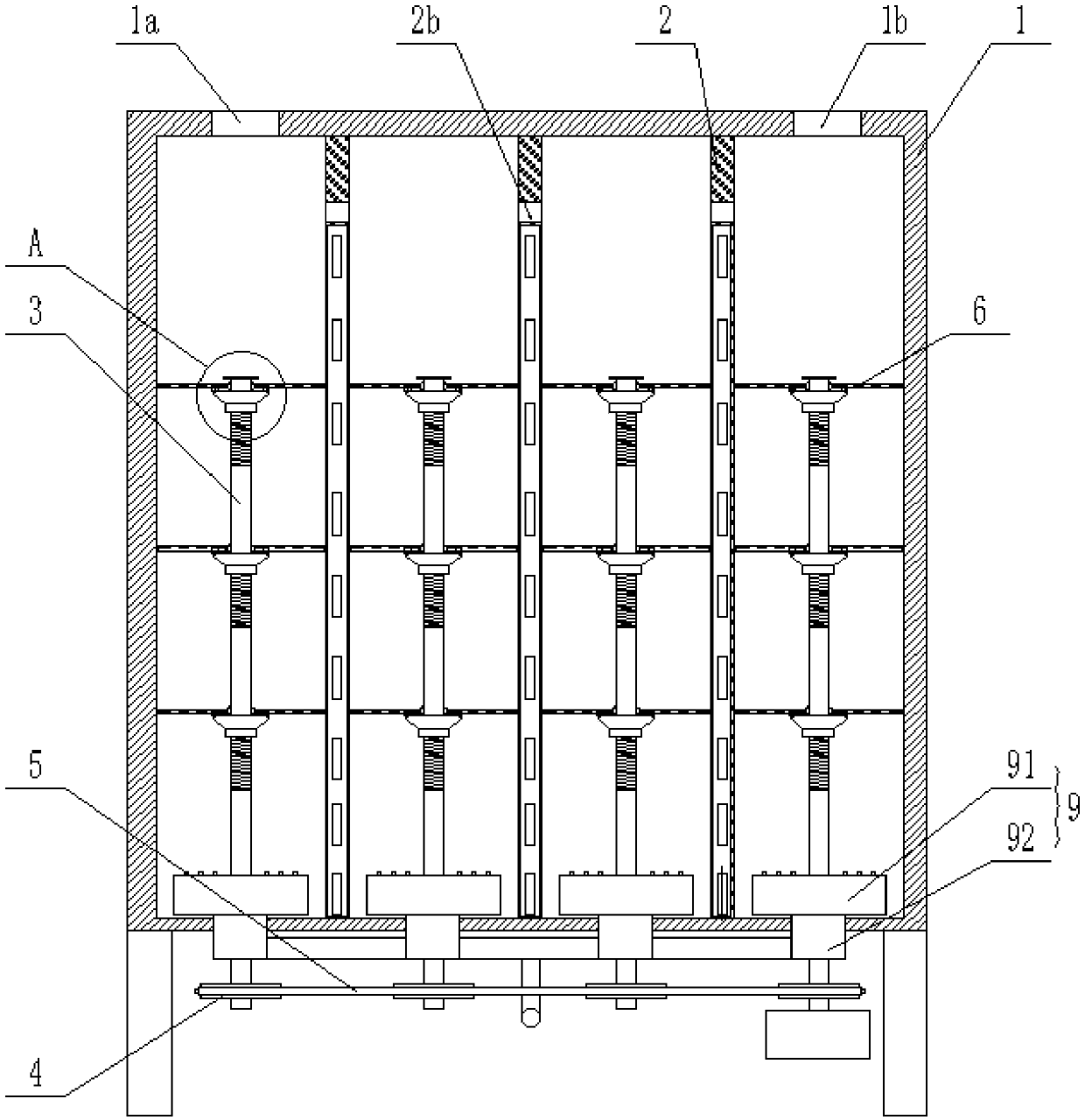
[0024] Such as Figure 1-3As shown in , a photocatalytic device for degrading printing and dyeing wastewater includes a pool body 1, three light source mounting plates 2 are vertically arranged in the pool body 1, and a light source 2a is arranged in the light source mounting plate 2, so The light source mounting plate 2 divides the pool body 1 into a plurality of mixed flow chambers, the upper part of the light source mounting plate 2 is provided with a liquid guide hole 2b, and the top of the pool body 1 is provided with a water inlet 1a and a water outlet 1b, The water inlet 1a and the water outlet 1b are respectively located in the two outer mixing chambers, a stirring shaft 3 is vertically pierced in the mixing chamber, and three swirl blade assemblies are arranged on the upper part of the stirring shaft 3, The lower part of the stirring shaft 3 is rotatably connected w...
Embodiment 2
[0031] Example 2 Photocatalytic device II for degrading printing and dyeing wastewater
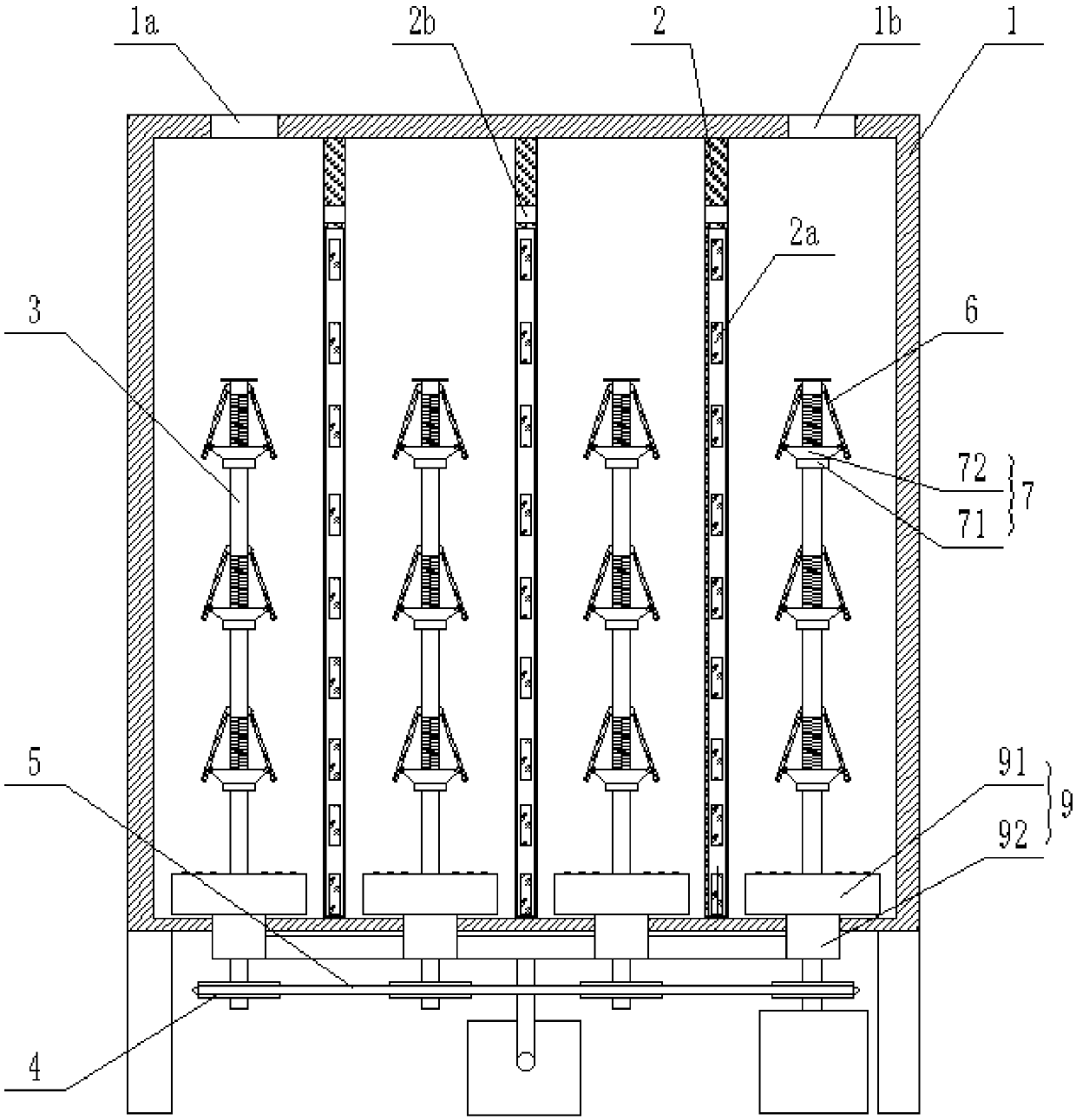
[0032] Such as Figure 1-3 As shown in , a photocatalytic device for degrading printing and dyeing wastewater includes a pool body 1, three light source mounting plates 2 are vertically arranged in the pool body 1, and a light source 2a is arranged in the light source mounting plate 2, so The light source mounting plate 2 divides the pool body 1 into a plurality of mixed flow chambers, the upper part of the light source mounting plate 2 is provided with a liquid guide hole 2b, and the top of the pool body 1 is provided with a water inlet 1a and a water outlet 1b, The water inlet 1a and the water outlet 1b are respectively located in the two outer mixing chambers, a stirring shaft 3 is vertically pierced in the mixing chamber, and three swirl blade assemblies are arranged on the upper part of the stirring shaft 3, The lower part of the stirring shaft 3 is rotatably connected with an aerati...
Embodiment 3
[0039] Example 3 Photocatalytic device III for degrading printing and dyeing wastewater
[0040] Such as Figure 1-3 As shown in , a photocatalytic device for degrading printing and dyeing wastewater includes a pool body 1, three light source mounting plates 2 are vertically arranged in the pool body 1, and a light source 2a is arranged in the light source mounting plate 2, so The light source mounting plate 2 divides the pool body 1 into a plurality of mixed flow chambers, the upper part of the light source mounting plate 2 is provided with a liquid guide hole 2b, and the top of the pool body 1 is provided with a water inlet 1a and a water outlet 1b, The water inlet 1a and the water outlet 1b are respectively located in the two outer mixing chambers, a stirring shaft 3 is vertically pierced in the mixing chamber, and three swirl blade assemblies are arranged on the upper part of the stirring shaft 3, The lower part of the stirring shaft 3 is rotatably connected with an aerat...
PUM
 Abstract
Description
Claims
Application Information
 - R&D
- Intellectual Property
- Life Sciences
- Materials
- Tech Scout
- Unparalleled Data Quality
- Higher Quality Content
- 60% Fewer Hallucinations
Browse by: Latest US Patents, China's latest patents, Technical Efficacy Thesaurus, Application Domain, Technology Topic, Popular Technical Reports.
© 2025 PatSnap. All rights reserved.Legal|Privacy policy|Modern Slavery Act Transparency Statement|Sitemap|About US| Contact US: help@patsnap.com