A drag reduction method for hypersonic vehicles based on the leading edge shock attenuation of synthetic jet wings

A hypersonic and synthetic jet technology, applied in aircraft, supersonic aircraft, drag reduction, etc., can solve the problems of difficulty in ensuring the overall stiffness, high development cost, and small amount of fuel that can be carried, and achieve easy electrical parameter control, structural Simple, drag-reducing effect

Inactive Publication Date: 2019-01-22
NAT UNIV OF DEFENSE TECH
View PDF6 Cites 17 Cited by
  • Summary
  • Abstract
  • Description
  • Claims
  • Application Information

AI Technical Summary

Problems solved by technology

[0005] 1) An increase in the amount of engine fuel or an increase in the speed requirement of the booster carrier's shift point will lead to an increase in the total weight of the weapon system, and a reduction in the overall maneuverability and survivability;
[0006] 2) Seeking a high lift-to-drag ratio design scheme through aerodynamic shape optimization leads to the development of a "flat" shape of the aircraft, resulting in a smaller filling space inside the aircraft, a small amount of fuel that can be carried, and high pressure for miniaturization of stand-alone equipment, poor versatility, and high development costs , a series of problems such as poor manufacturing and assembly process of the whole aircraft, difficulty in guaranteeing the overall rigidity, etc.

Method used


Image

  • A drag reduction method for hypersonic vehicles based on the leading edge shock attenuation of synthetic jet wings
  • A drag reduction method for hypersonic vehicles based on the leading edge shock attenuation of synthetic jet wings
  • A drag reduction method for hypersonic vehicles based on the leading edge shock attenuation of synthetic jet wings

Examples


Embodiment Construction

[0029] Attached below Figure 1 to Figure 4 , the embodiment of the present invention will be further described in detail.

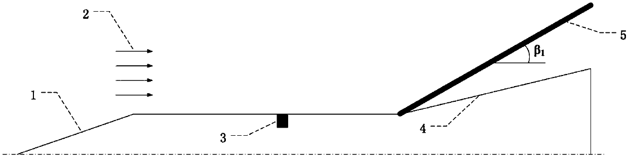
[0030] refer to figure 1 , during the flight of the hypersonic vehicle 1, under the interaction between the high-speed free flow 2 and the hypersonic vehicle 1, an oblique shock wave is formed on the flank 4 of the hypersonic vehicle, that is, the flank oblique shock wave 5. In the state of athermal jet control Next, the distance between the flank oblique shock 5 and the hypersonic vehicle’s flank 4 is relatively close, the flank oblique shock 5 is stronger, the pressure behind the flank oblique shock 5 is greater, and the resistance on the flank surface of the hypersonic vehicle is greater. Bring greater resistance to the flight of hypersonic aircraft.

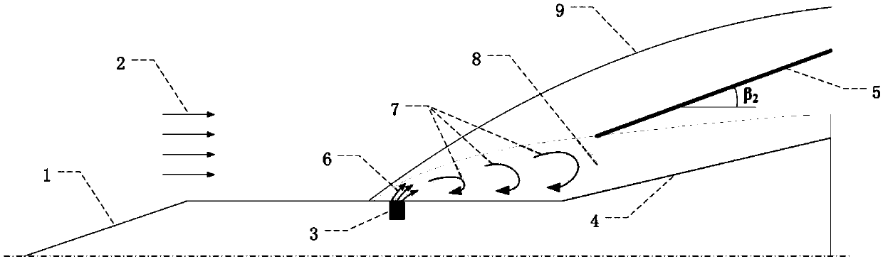
[0031] refer to figure 2 , the present invention provides a hypersonic vehicle drag reduction method based on synthetic jet wing leading edge shock wave weakening, and a plasma synthetic jet exciter...


PUM


Abstract

A drag reduction method for hypersonic vehicles based on the leading edge shock attenuation of synthetic jet wing is proposed. A plasma synthetic jet actuator is installed upstream of the hypersonic vehicle flank. During the flight of hypersonic vehicle, the plasma synthetic jet actuator is turned on to generate discharge in the cavity of the plasma synthetic jet actuator, which causes the gas inthe cavity of the actuator to expand by heat and eject out at high speed to generate high-speed gas hot jet. Under the interaction of high-speed gas hot jet and hypersonic free-coming flow; the jet interaction shock wave, large-scale vortex structure and local relative high temperature region weaken the oblique shock wave intensity, reduce the oblique shock wave angle, raise the shock foot and reduce the pressure on the outer surface of the hypersonic vehicle side wing, thus achieving the purpose of reducing the drag of the hypersonic vehicle. The invention effectively reduces the drag of thehypersonic vehicle without placing higher requirements on the power system or the booster and the aircraft configuration.

Description

technical field [0001] The invention relates to the field of hydrodynamic flow control and the field of gas discharge application, and relates to a method for reducing drag of a hypersonic aircraft based on the weakening of shock waves at the leading edge of a synthetic jet wing. Background technique [0002] Hypersonic vehicle technology is a new commanding height in the field of aerospace technology in the 21st century. It is the third epoch-making milestone in the history of human aerospace after the invention of aircraft and breaking the sound barrier. It will also open up a new way for humans to enter space. [0003] Hypersonic aircraft has the characteristics of long flight distance, strong maneuverability, and high penetration probability. It can obtain the ability to ensure space entry, effective use of space, and space control, and can effectively contain enemy ground, airborne, and shipborne early warning and weapon systems. The overall function can effectively att...

Claims


Application Information

Patent Timeline
IPC IPC(8): B64C23/00B64C23/06B64C30/00
CPCB64C23/00B64C23/06B64C30/00Y02T50/10
Inventor 罗振兵周岩夏智勋王林邓雄刘强
Owner NAT UNIV OF DEFENSE TECH
Why Eureka
Try Eureka