A motor disassembly tooling and disassembly method
A technology for dismantling tooling and motors, which is applied in the direction of electromechanical devices, manufacturing motor generators, electrical components, etc., can solve the problems that the whole motor cannot be disassembled rationally, and achieve the effect of optimizing the disassembly tooling structure, convenient operation, and fast disassembly
- Summary
- Abstract
- Description
- Claims
- Application Information
AI Technical Summary
Problems solved by technology
Method used
Image
Examples
Embodiment 1
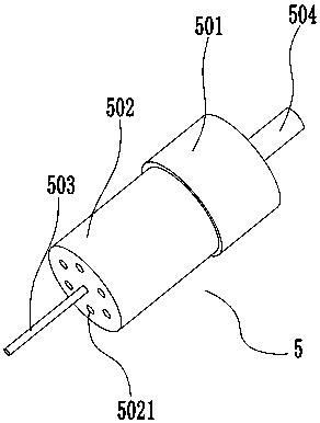
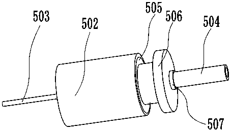
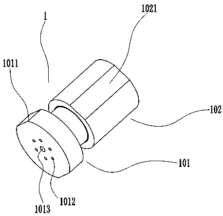
[0043] Such as Figure 1-10 , a motor disassembly tooling of the present invention, a motor disassembly tooling, comprising a first disassembly tool 1, a second disassembly tool 2, a third disassembly tool 3 and a fourth disassembly tool 4:
[0044] The first disassembly tool 1 includes a fixed part 101 that can relatively move in the axial direction, a moving part 102 and several screw rods. The fixed part 101 and the moving part 102 are connected to form a cavity that matches the motor. The cavity The diameter is larger than the diameter of the motor casing 502 and smaller than the diameter of the motor protection cap 501. The fixed part 101 is provided with several threaded holes 1012. The threaded holes 1012 are matched with the threaded holes 5021 of the motor casing and the screw. There is also a through hole 1013 for the passage of the motor shaft 503;
[0045] The second disassembly tool 2 includes a base one, a clamping member 204 and a thimble 205 installed on the b...
Embodiment 2
[0050] In this embodiment, the difference from Embodiment 1 is that the connection between the fixed part 101 and the moving part 102 is a threaded connection, the outer wall of the thimble 205 and the inner wall of the round hole are provided with matching threads, and the thimble 2 306 The outer wall and the inner wall of the round hole three are provided with matching threads, and the outer wall of the thimble three 403 and the inside of the round hole four are provided with matching threads. And without continuous force, the operation is more convenient and saves time and effort.
Embodiment 3
[0052] Such as Figure 5-10 As shown, in this embodiment, the difference from Embodiment 1 is that the ends of the thimble 1 205, thimble 2 306, and thimble 3 403 are all set as hexagonal screw heads or hexagonal flange heads or with side holes, and each The end of the thimble is set as a hexagonal screw head or a hexagonal flange head, and an auxiliary screwdriver, small wrench, etc. can be used to rotate each thimble, which makes the operation more convenient and labor-saving.
PUM
 Abstract
Description
Claims
Application Information
 - R&D Engineer
- R&D Manager
- IP Professional
- Industry Leading Data Capabilities
- Powerful AI technology
- Patent DNA Extraction
Browse by: Latest US Patents, China's latest patents, Technical Efficacy Thesaurus, Application Domain, Technology Topic, Popular Technical Reports.
© 2024 PatSnap. All rights reserved.Legal|Privacy policy|Modern Slavery Act Transparency Statement|Sitemap|About US| Contact US: help@patsnap.com


