A power capacitor closing inrush current suppression device and method

A technology for power capacitors and inrush current suppression, applied in circuit devices, emergency protection circuit devices, emergency protection circuit devices for limiting overcurrent/overvoltage, etc., can solve problems such as unsatisfactory inrush current suppression, and achieve flexible and diverse charging methods , Easy to transport and install, with obvious inhibitory effect

Pending Publication Date: 2019-01-18
GLOBAL ENERGY INTERCONNECTION RES INST CO LTD +1
View PDF0 Cites 0 Cited by
  • Summary
  • Abstract
  • Description
  • Claims
  • Application Information

AI Technical Summary

Problems solved by technology

[0004] Therefore, the present invention provides a power capacitor closing inrush suppression device and method, which overcomes the defects of unsatisfactory inrush suppression in the prior art

Method used


Image

  • A power capacitor closing inrush current suppression device and method
  • A power capacitor closing inrush current suppression device and method
  • A power capacitor closing inrush current suppression device and method

Examples


Embodiment 1

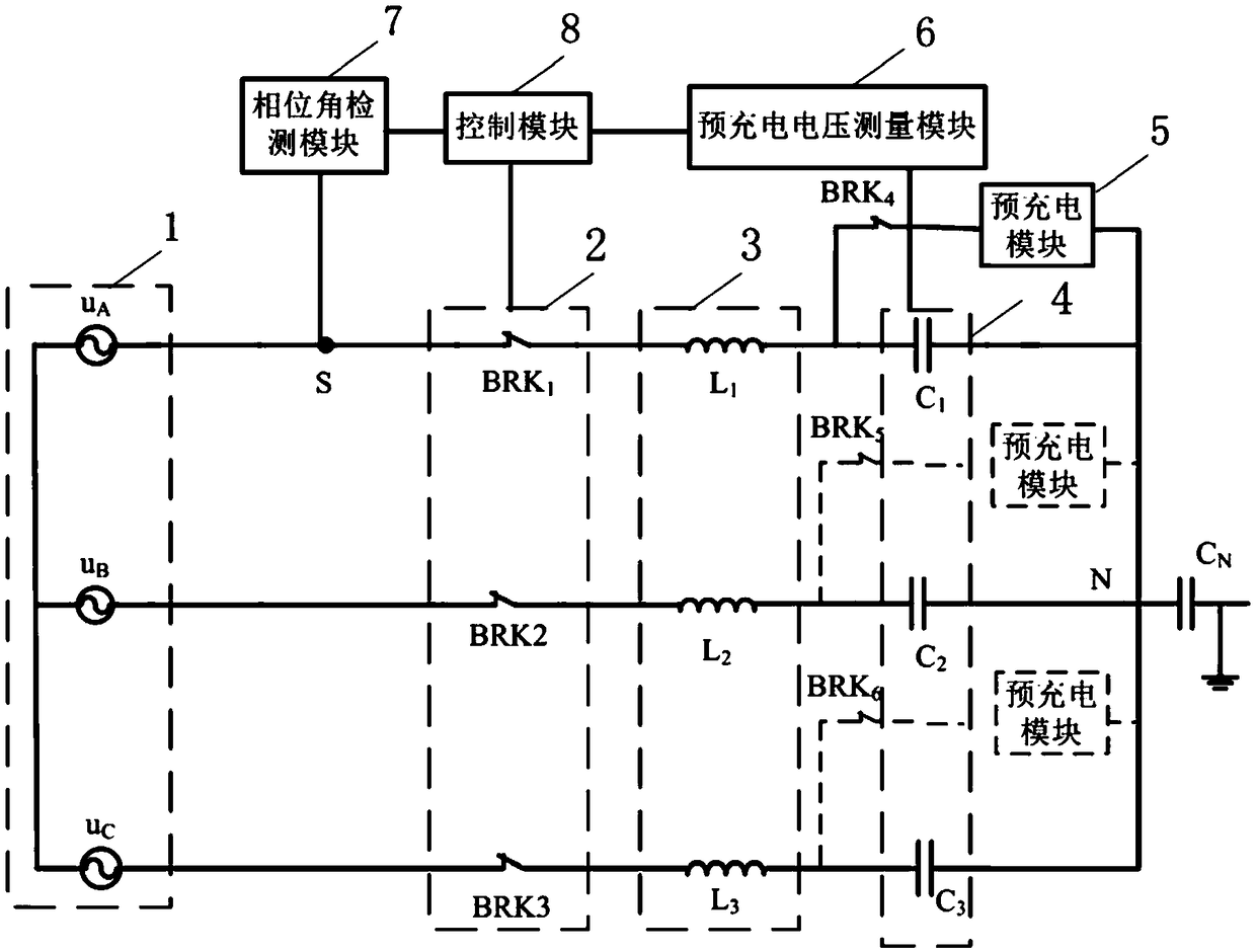
[0054] An embodiment of the present invention provides a power capacitor closing inrush suppression device, which is applied to an AC distribution network, such as figure 1 As shown, the AC distribution network includes a three-phase AC power supply 1, a three-phase circuit breaker 2, a series reactor 3, and a three-phase capacitor 4. The above-mentioned power capacitor closing inrush current suppression device includes: a pre-charging module 5, a pre-charging voltage measurement module 6. Phase angle detection module 7 and control module 8 . In the embodiment of the present invention, the three-phase AC power supply 1 is connected to a star-shaped neutral point with an ineffective ground connection, and the reactive power compensation side of the three-phase capacitor 4 is connected to a star-shaped neutral point with an ineffective ground connection.

[0055] In the implementation of the present invention, as figure 1 As shown, the circuit breakers BRK1-BRK3 are three-phase...

Embodiment 2

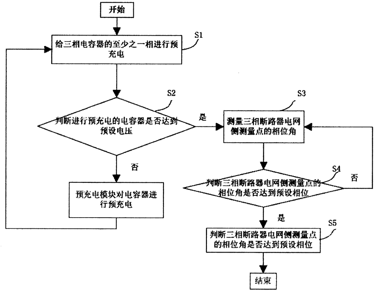
[0081] An embodiment of the present invention provides a power capacitor closing inrush suppression method. In practical applications, it can be specifically applied to the power capacitor closing inrush suppression device described in the above-mentioned embodiment 1, such as image 3 As shown, the power capacitor closing inrush suppression method mainly includes the following steps:

[0082] Step S1: pre-charging at least one phase of the three-phase capacitor. In the embodiment of the present invention, the pre-charging module can pre-charge the capacitors connected to each phase branch of the three-phase AC power supply with single-phase, two-phase or three-phase capacitors. In practical applications, there are multiple options according to engineering requirements.

[0083] Step S2: judging whether the pre-charged capacitor reaches a preset voltage. In the embodiment of the present invention, the pre-charging voltage measurement module monitors the voltage on the capacit...


PUM


Abstract

The invention discloses a power capacitor closing inrush current suppression device and method. Before the three-phase circuit breaker is closed, at least one phase of the three-phase capacitor is precharged. When the voltage of both terminals of the precharged capacitor is charged to the preset voltage, the phase angle of the measuring point on the grid side of the three-phase circuit breaker ismeasured. When the phase angle of the measuring point on the grid side of the three-phase circuit breaker reaches the preset phase, the three-phase circuit breaker is controlled to close and put in the three-phase capacitor. An embodiment of the present invention eliminates the transient component of the current in the circuit after the capacitor is switched on by precharging, Thus, after the three-phase capacitor is put into the circuit, the current enters into the steady state quickly without passing through the transient process or passing through the very short transient process, therebyrealizing the inrush current suppression of the closing, and the capacitor can be precharged with single-phase, two-phase or three-phase, and the charging mode is flexible and diverse.

Description

technical field [0001] The invention relates to the technical field of power control, in particular to a device and method for suppressing closing inrush current of a power capacitor. Background technique [0002] As an important reactive power compensation device in the power system, the shunt capacitor bank is used to improve the power factor of the power grid and improve the power quality. Because of its low cost, easy installation and maintenance, it has become the most widely used in the current power system. One of reactive power compensation devices. [0003] The transient phenomenon during the input process of the parallel capacitor bank will lead to a large closing inrush current. The closing inrush is generated because when the capacitor is in an uncharged state, the current flowing through the capacitor at the moment of closing is only limited by its loop impedance, and at this time the impedance of the loop is extremely small, so the generated closing inrush is ...

Claims


Application Information

Patent Timeline
IPC IPC(8): H02J3/18H02H9/02
CPCH02H9/02H02J3/18Y02E40/30
Inventor 邓占锋陈星彤戴朝波
Owner GLOBAL ENERGY INTERCONNECTION RES INST CO LTD
Why Eureka
Try Eureka