
Miniaturized anti-high overload linear polarization single helical antenna

A single-spiral, linearly polarized technology, applied in the directions of the antenna support/installation device, the structural connection of the antenna grounding switch, the structural form of the radiating element, etc. Resistance increases and other problems, to achieve the effect of taking into account the requirements of mechanical and electrical parameters

Active Publication Date: 2019-01-18
SUZHOU BOHAI CHUANGYE MICRO SYST
View PDF8 Cites 2 Cited by
  • Summary
  • Abstract
  • Description
  • Claims
  • Application Information

AI Technical Summary

Problems solved by technology

[0004] In the development of missile-borne antennas, there are contradictory disadvantages in the mechanical and electrical parameters of the antenna: reducing the size of the antenna will reduce the mass and aerodynamic resistance of the antenna, but the efficiency of the antenna will decrease, the electrical breakdown strength will decrease and the passband of the antenna will decrease. Narrowing; increasing the size of the antenna increases the directivity of the antenna, but the aerodynamic resistance of the antenna increases

Method used


Image

  • Miniaturized anti-high overload linear polarization single helical antenna
  • Miniaturized anti-high overload linear polarization single helical antenna
  • Miniaturized anti-high overload linear polarization single helical antenna

Examples


Embodiment Construction

[0015] In order to describe the structure and features of the present invention in detail, the following preferred embodiments are given and described below with accompanying drawings.

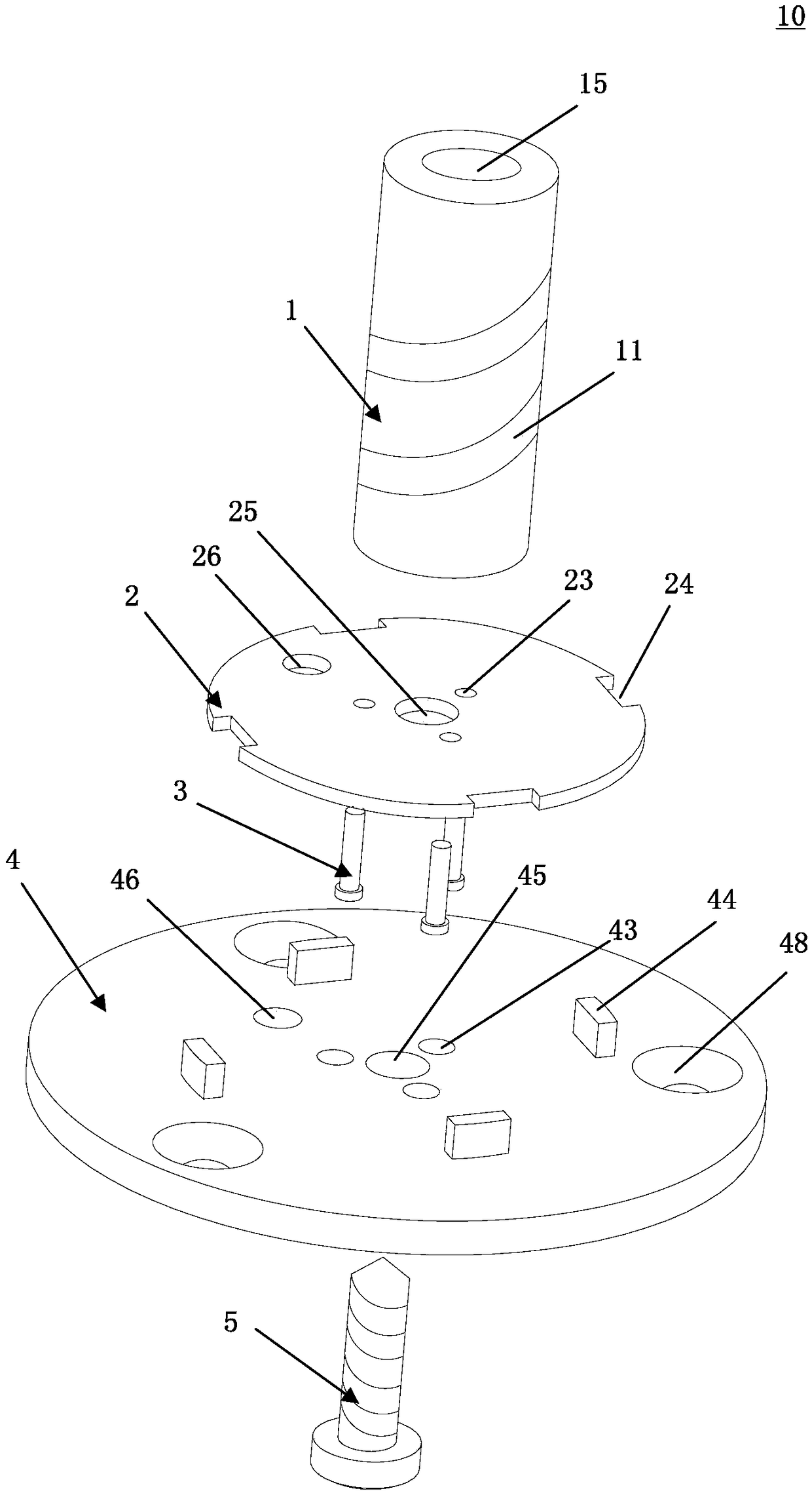
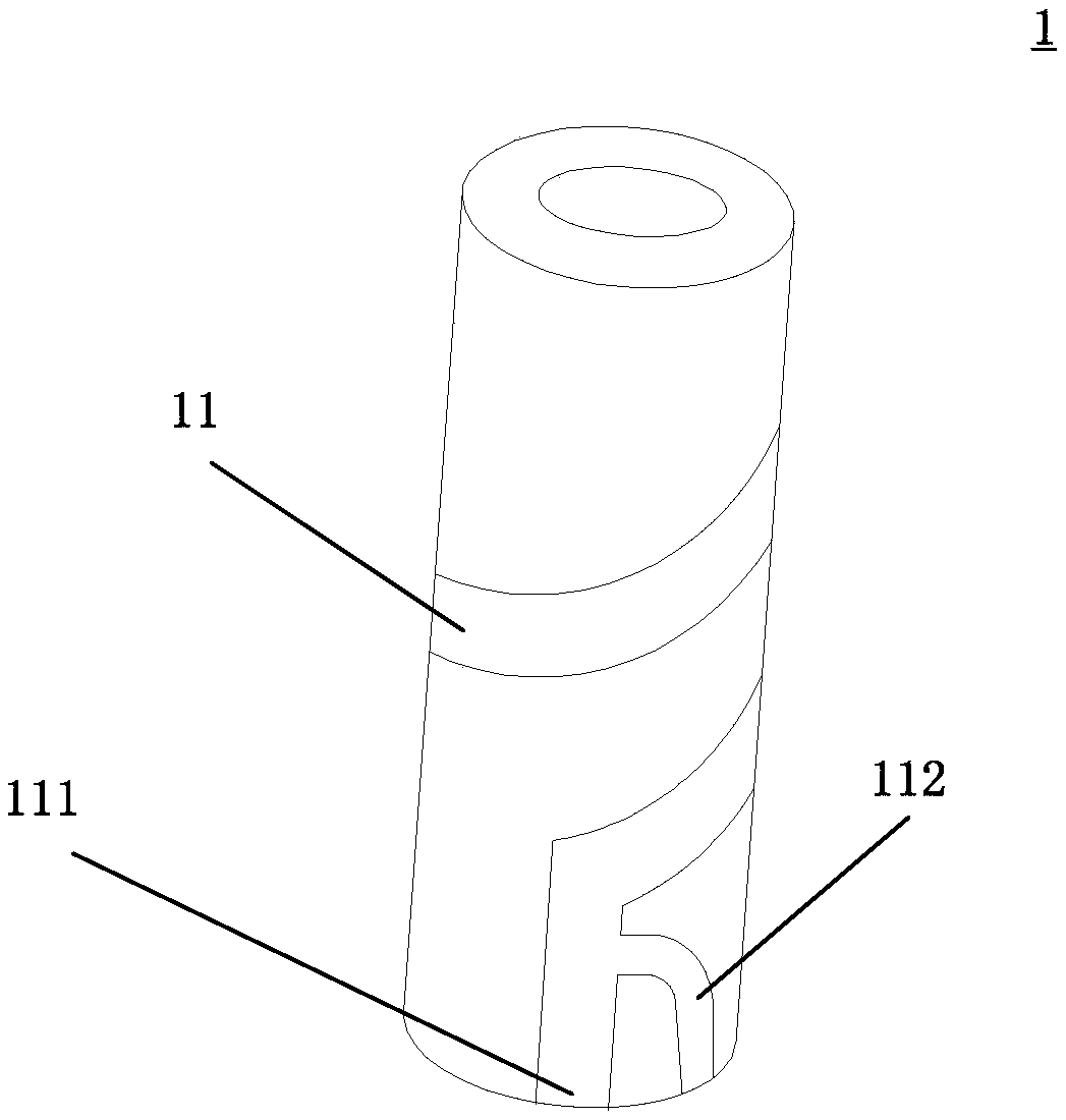
[0016] see Figure 1 to Figure 3 , figure 1 It is a schematic diagram of the combined three-dimensional structure of the miniaturized anti-high overload linearly polarized single helical antenna of the present invention. figure 2 It is a schematic diagram of the decomposed three-dimensional structure of the miniaturized anti-high overload linearly polarized single helical antenna of the present invention. image 3 It is a structural representation of a deformation design of the antenna post in the miniaturized anti-high overload linearly polarized single helical antenna of the present invention. The present invention proposes a miniaturized anti-high overload linearly polarized single helical antenna 10 , which includes: antenna post 1 , low noise amplifier circuit board 2 , anti-rotation n...


PUM


Abstract

The invention provides a miniaturized anti-high-overload linear polarization single helical antenna, which comprises an antenna post, a low-noise amplifying circuit board, an anti-rotation nail, a riveting sleeve and a fixing screw. Wherein the low-noise amplifier circuit board is sandwiched between the antenna pillar and the riveting sleeve; the antenna pillar, the low-noise amplifier circuit board and the riveting sleeve are stacked together and fixed together by the fixing screws, and the anti-rotation nail is matched with the antenna pillar to prevent the antenna pillar from rotating. theantenna can give good consideration to the mechanical and electrical parameters of the antenna.

Description

technical field [0001] The present invention relates to antennas, in particular to missile-borne antennas. [0002] Background technique [0003] With the continuous improvement of modern high-tech warfare on the performance requirements of missiles and the special application environment of missiles, more special requirements are put forward for missile-borne antennas. The missile-borne antenna must have specific electrical indicators, suitable structural form, satisfactory mechanical strength and the ability to work normally in harsh environments without affecting the aerodynamic shape and flight performance of the missile. This requires the missile-borne antenna to be small in size, light in weight, and good in mechanical strength and rigidity. [0004] In the development of missile-borne antennas, there are contradictory disadvantages in the mechanical and electrical parameters of the antenna: reducing the size of the antenna will reduce the mass and aerodynamic res...

Claims


Application Information

Patent Timeline
Patent Type & Authority Applications(China)
IPC IPC(8): H01Q1/12H01Q1/38H01Q1/50
CPCH01Q1/12H01Q1/38H01Q1/50Y02D30/70
Inventor 张霄鹏黄勇陈仁军李成钊汪杰
Owner SUZHOU BOHAI CHUANGYE MICRO SYST
Learn More