A control system and method for laser radar galvanometer servo motor

A technology of servo motor and laser radar, which is applied in general control system, control/adjustment system, computer control, etc., can solve the problems of no advantages in speed and precision indicators, complex neural network control, and low speed indicators, etc., and reach the target area range The effect of wide, fast response and large scanning angle

Active Publication Date: 2021-04-13
NANJING UNIV OF SCI & TECH
View PDF6 Cites 0 Cited by
  • Summary
  • Abstract
  • Description
  • Claims
  • Application Information

AI Technical Summary

Problems solved by technology

The PID adjustment method is the most widely used in technology, but it is also the most inaccurate control; fuzzy control does not control a specific model, although it is universal, but has no advantages in speed and accuracy indicators; neural network control is very complicated, resulting in The speed index is not high, and it is only suitable for high-precision control schemes

Method used


Image

  • A control system and method for laser radar galvanometer servo motor
  • A control system and method for laser radar galvanometer servo motor
  • A control system and method for laser radar galvanometer servo motor

Examples


Embodiment 1

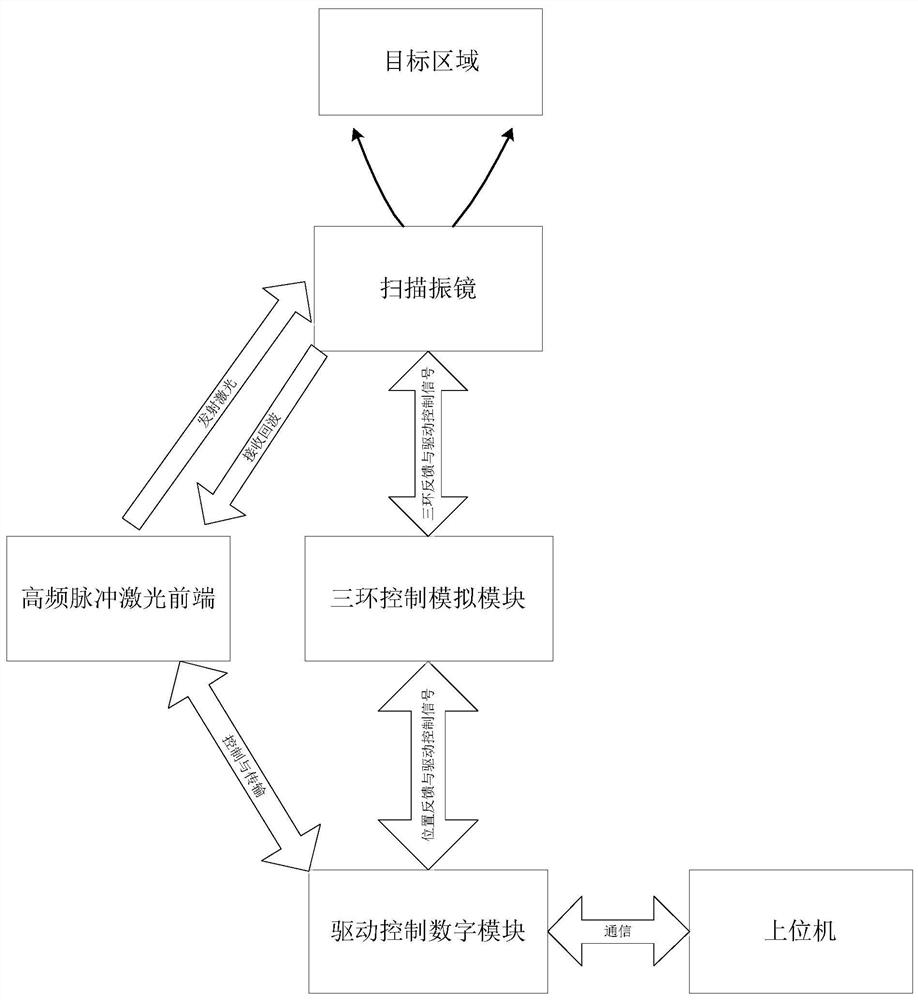
[0062]This embodiment is directed to the control system of the laser radar spray hammer motor, including:

[0063]1) Select high-frequency laser front end to generate high-frequency lasers, using high sensitivity detectors to receive laser ranging echo;

[0064]2) Use the scanning gammery to change the laser light path to periodically scan the designated area;

[0065]3) Pass the resulting laser beam position and target distance information to the host computer by driving the control digital module;

[0066]4) The upper machine draws the point cloud image of the specified area through three-dimensional reconstruction software.

[0067]The servo drive control system consists of a driving control digital module and a three-ring control analog module, and the drive control digital module consists of ARM, FPGA. The drive control digital module has a function of generating a drive signal, a processing feedback signal, a state of determining a system, and selecting a control policy.

[0068]figure 1 It is ...


PUM


Abstract

The invention discloses a control system and method for a laser radar vibrating mirror servo motor. The system includes a host computer, a drive control digital module, a three-ring control analog module, a high-frequency pulse laser front end, and a scanning galvanometer. The drive control digital module includes a master control ARM unit and an FPGA unit connected to each other; the method is: After the mirror servo motor starts to work smoothly, it is judged whether the system is scanning in the highest performance working mode, and the mode is judged according to the set threshold, and two index improvement methods are adopted: in the mode of smooth speed operation, the introduction of interpolation module to drive The resolution of the control signal is improved to achieve the purpose of high-precision scanning; in the high-speed scanning mode, the repeated tracking cumulative error control unit is introduced to perform multi-cycle error collection and correction to achieve the purpose of improving accuracy. The invention ensures that the high-precision three-dimensional imaging scanning system can run stably and efficiently at high speed.

Description

Technical field[0001]The present invention relates to a laser radar spray triumist motor technology, particularly a control system and method for a laser radar spray hammer motor.Background technique[0002]The vibratory servo system is widely used in industrial engineering in laser marking, laser positioning and other industrial engineering, and there is also a large use in a three-dimensional scan imaging system. The optical scanning head of the vibrating mirror system is a position where the servo system is to change the motor deflection angle, thereby changing the laser emission receiving optical path, and finally override the designated area.[0003]Most of the way to drive the control of the controlling mirror motor is used to use an external circuit to perform digital-to-analog conversion, generating an analog period signal such as a sine wave or triangular wave, and drive the gammell motor. The speed and accuracy of the servo motor is a bottleneck problem that restricts the enti...

Claims


Application Information

Patent Timeline
Patent Type & Authority Patents(China)
IPC IPC(8): G05B19/042
CPCG05B19/0423G05B2219/25314
Inventor 王春勇李尚文李振华严伟来建成纪运景
Owner NANJING UNIV OF SCI & TECH
Why Eureka
Try Eureka